SLVA720A July 2015 – October 2020 CD14538B , CD14538B-MIL , CD4047B , CD4047B-MIL , CD4098B , CD4098B-MIL , CD54HC123 , CD54HC221 , CD54HC4538 , CD54HCT123 , CD54HCT4538 , CD74HC123 , CD74HC221 , CD74HC423 , CD74HC4538 , CD74HC4538-Q1 , CD74HCT123 , CD74HCT221 , CD74HCT423 , CD74HCT4538 , SN54121 , SN54123 , SN54221 , SN54AHC123A , SN54AHCT123A , SN54LS123 , SN54LS123-SP , SN54LS221 , SN74121 , SN74221 , SN74AHC123A , SN74AHC123A-EP , SN74AHCT123A , SN74LS122 , SN74LS123 , SN74LS221 , SN74LS423 , SN74LV123A , SN74LV123A-EP , SN74LV123A-Q1 , SN74LV221A , SN74LV221A-Q1 , SN74LVC1G123
- 1Introduction
- 2Terminology
- 3Theory of Operation
- 4Applications
-
5Frequently Asked Questions
- 5.1 How do I calculate the output pulse length?
- 5.2 How do I configure the SN74LVC1G123's inputs for ______ edge triggering?
- 5.3 How stable is the output pulse length over VCC changes?
- 5.4 How stable is the output pulse length over temperature changes?
- 5.5 Which inputs of the SN74LVC1G123 have Schmitt-triggers?
- 5.6 Can I connect the Cext pin to ground?
- 6Revision History
4.1.1 Pulse Length Determination
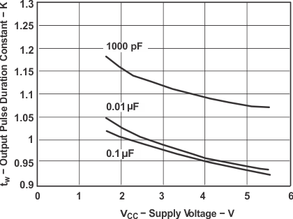
The output pulse length is the most important factor for the design of a monostable multivibrator circuit in most applications. Some systems might require only a few microseconds of output, while others might require seconds or even minutes. Any monostable multivibrator’s datasheet should contain several useful graphics to help with this process. Since we are using SN74LVC1G123 as an example, the graphics from that datasheet are included here for reference.
 Figure 4-1 Output Pulse Duration vs External Timing Capacitance, SN74LVC1G123
 Figure 4-3 Minimum Retrigger Time vs Supply Voltage
 Figure 4-2 Output Pulse Duration Constant vs Supply Voltage
One thing to notice on these plots is that only specific values of resistors and capacitors were tested for the datasheet. It is recommended to use one of the tested capacitor values to make calculations faster, easier, and more accurate. Several examples will be shown in Section 4.2 using these graphics as reference.