SNVU849A May 2023 – September 2024 LP5890 , LP5891 , LP5891-Q1 , LP5899-Q1 , TLC6983 , TLC6984
3.4 Diagnostics
The sample code provides an API to detect which LED drivers have LED open (LOD) and which LED drivers have LED short (LSD) faults. In addition, when the sample code is paired with LP5899DYYEVM, the faults detected by the LP5899 augmented connectivity device are read. Within the TLC698x_LP589x_APIs.h file the prototype of the API is defined.
void LED_Update_Chip_Status(void);This API updates the variable chip_status which is defined in system_info.h.
struct ccsiBusStatus {
    uint16_t LSD;             // LED Short Detection
    uint16_t LOD;             // LED Open Detection
    volatile outChannel LOD_channels[TOTAL_SCAN_LINES];
    volatile outChannel LSD_channels[TOTAL_SCAN_LINES];
};

struct chipStatus {
    struct ccsiBusStatus busStatus[MAX_CASCADED_UNITS];
#ifdef _TLC6989_LP5899
    uint16_t ERR;                  // LP5899/TLC6989 Global error flag
    uint16_t POR;                  // Power-On-Reset flag
    uint16_t OSC;                  // Internal oscillator flag
    uint16_t OTP_CRC;              // OTP CRC flag
    uint16_t DEV_STATE;            // Device state
    uint16_t SPI_CRC;              // SPI CRC error
    uint16_t SPI_REG_WRITE;        // SPI register write error
    uint16_t SPI;                  // SPI error
    uint16_t SPI_CS;               // SPI Chip Select (CS) pin error
    uint16_t SPI_TIMEOUT;          // SPI reset timeout error
    uint16_t SRST;                 // Softreset error
    uint16_t DRDY_STATUS;          // DRDY pin status
    uint16_t RXFF;                 // Receive FIFO error
    uint16_t RXFFSED;              // Receive FIFO single error detection
    uint16_t RXFFUVF;              // Receive FIFO underflow
    uint16_t RXFFOVF;              // Receive FIFO overflow
    uint16_t TXFF;                 // Transmit FIFO error
    uint16_t TXFFSED;              // Transmit FIFO single error detection
    uint16_t TXFFUVF;              // Transmit FIFO underflow
    uint16_t TXFFOVF;              // Transmit FIFO overflow
    uint16_t CCSI;                 // CCSI interface error
    uint16_t CCSI_SIN;             // CCSI missing toggling on SIN error
    uint16_t CCSI_CRC;             // CCSI data CRC error
    uint16_t CCSI_CHECK_BIT;       // CCSI check bit error
    uint16_t CCSI_CMD_QUEUE_OVF;   // CCSI command queue overflow
#endif
};

// For diagnostics
extern struct chipStatus chip_status[CCSI_BUS_NUM];
Note that in the sample code the diagnostics is only executed during simple test mode and not during animation mode.
The variable chip_status can be watched in the Expressions view during the debug of the code by following the steps in Watching Variables, Expressions, and Registers. An example for the LP5891Q1EVM without any error is depicted in Figure 3-4. The first index of variable chip_status is the CCSI chain index. On the EVM only 1 chain is used. For the flags of the LED drivers, the busStatus variable is used which has an index for each LED driver in the chain.
 Figure 3-4 Example of Watching Expression
chip_status Without Errors
Figure 3-4 Example of Watching Expression
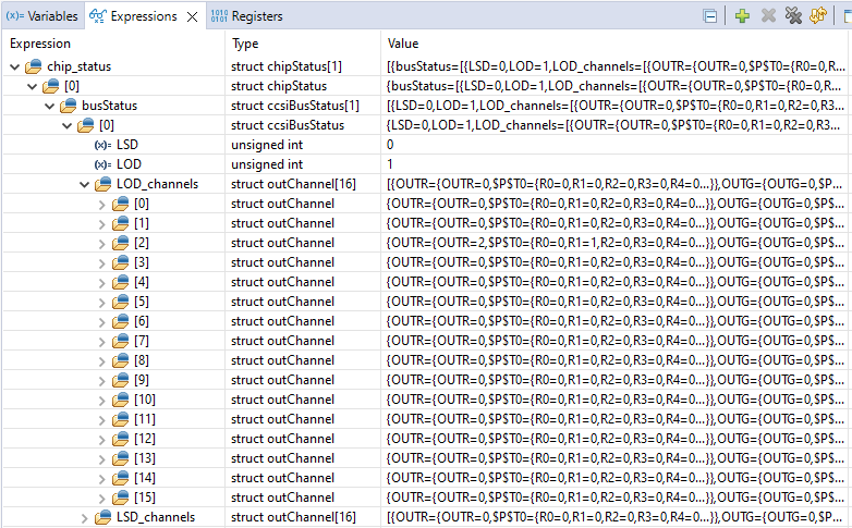
chip_status Without ErrorsFigure 3-5 depicts an expanded view of the chip_status variable. For each LED driver device in the chain, the LSD and LOD are shown. In addition, for the LSD and LOD faults the actual line and output channel which has the fault can be found. The LP5891Q1EVM uses 16 scan lines. Therefore, the indices for array LOD_channels run from 0 to 15.
 Figure 3-5 Example Showing Expanded Scan Lines of
Expression chip_status With LOD
Figure 3-5 Example Showing Expanded Scan Lines of
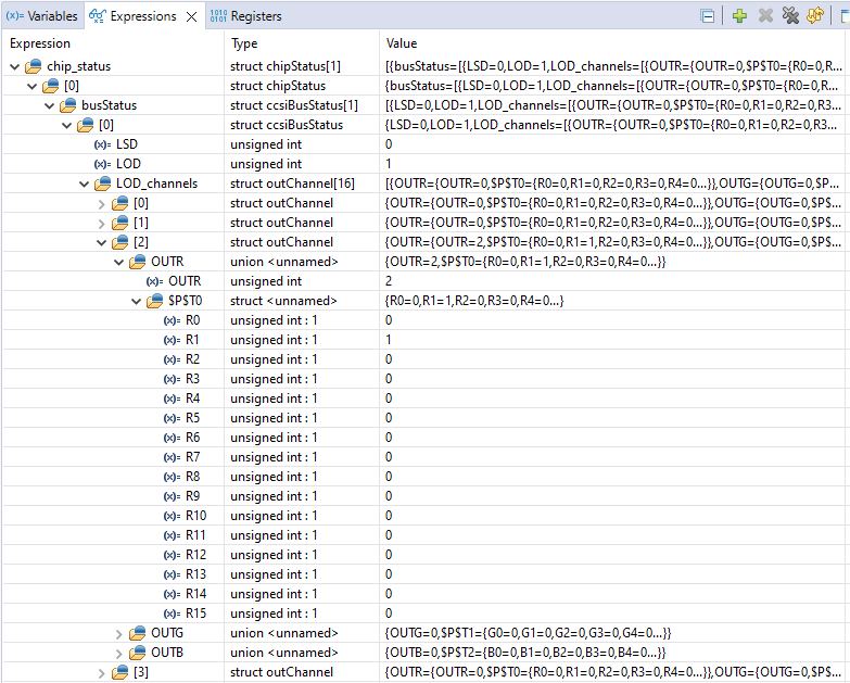
Expression chip_status With LODAn example of an LOD fault is depicted in Figure 3-6. In this example chip index 0 has an LOD fault. When array LOD_channels is expanded, it shows that the fault occurs on line with index 2. When that index is expanded, it shows that the fault happens on pin R1.
 Figure 3-6 Example Showing Expanded Channels of
Expression chip_status With LOD
Figure 3-6 Example Showing Expanded Channels of
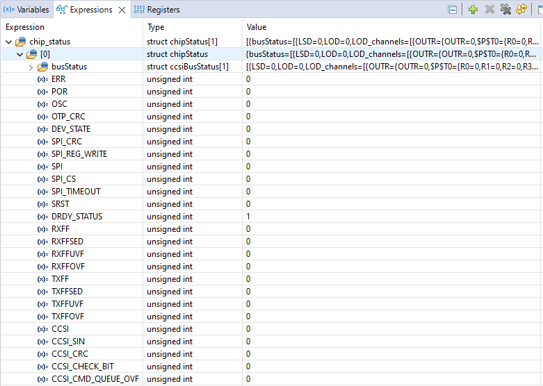
Expression chip_status With LODWhen the LP5899DYYEVM is used to pair with LP589x(-Q1), the chip_status variable also shows the error flags of the augemented connectivity IC. An example without any fault is depicted in Figure 3-7. For each CCSI chain (first index of chip_status) the error flags are listed. Note that DRDY_STATUS is one, because when LP5899 has data that is ready to be read, this value becomes zero.
 Figure 3-7 Example of chip_status Without Errors
When Paired With LP5899
Figure 3-7 Example of chip_status Without Errors
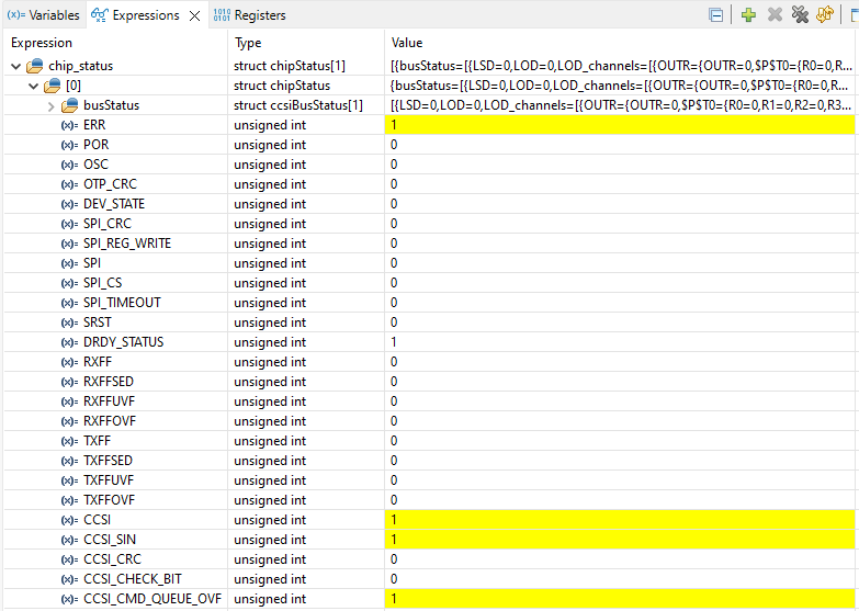
When Paired With LP5899An example of a CCSI fault is depicted in Figure 3-8. In this example, the SIN pin is stuck-at high while CCSI transmission is continued, which also results in an overflow for the CCSI command queue.
 Figure 3-8 Example Showing Expression chip_status
With CCSI Fault When Paired With LP5899