SLAAEI3 February 2024 MSPM0C1103 , MSPM0C1103-Q1 , MSPM0C1104 , MSPM0C1104-Q1 , MSPM0G1105 , MSPM0G1106 , MSPM0G1107 , MSPM0G1505 , MSPM0G1506 , MSPM0G1507 , MSPM0G3105 , MSPM0G3105-Q1 , MSPM0G3106 , MSPM0G3106-Q1 , MSPM0G3107 , MSPM0G3107-Q1 , MSPM0G3505 , MSPM0G3505-Q1 , MSPM0G3506 , MSPM0G3506-Q1 , MSPM0G3507 , MSPM0G3507-Q1 , MSPM0G3519 , MSPM0L1105 , MSPM0L1106 , MSPM0L1227 , MSPM0L1228 , MSPM0L1228-Q1 , MSPM0L1303 , MSPM0L1304 , MSPM0L1304-Q1 , MSPM0L1305 , MSPM0L1305-Q1 , MSPM0L1306 , MSPM0L1306-Q1 , MSPM0L1343 , MSPM0L1344 , MSPM0L1345 , MSPM0L1346 , MSPM0L2227 , MSPM0L2228 , MSPM0L2228-Q1
4.1 Test Environment Setup
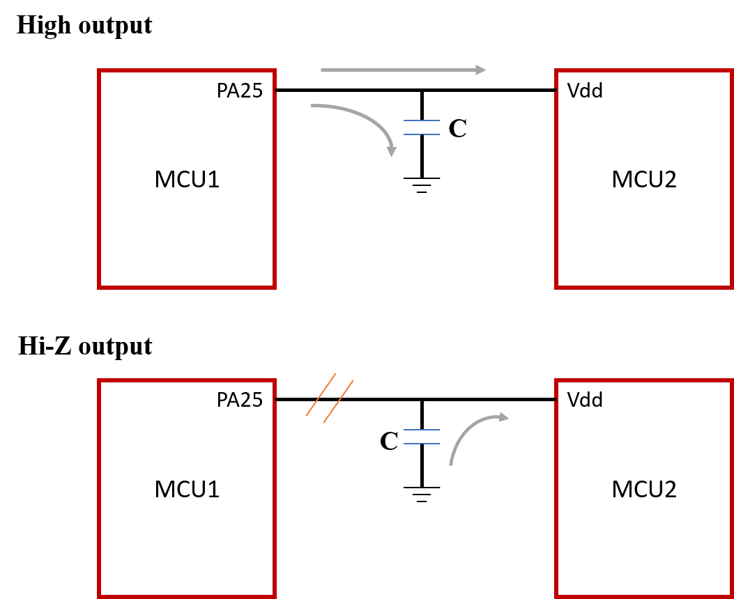
To verify the feasibility of Equation 2, it is necessary to first test the normal operation time of the MCU with a 3.3V capacitor supply. Thus, the following method is adopted. As shown in Figure 4-1, by changing the state of MCU1's PA25 pin, the power-down condition of MCU2 is simulated. Specifically, when the PA25 output is high, MCU2 supplies power normally, while charging the capacitor to reach 3.3V. When PA25 is in a high-impedance state, it can be considered that the power supply is disconnected at this time. Thus, MCU2 relies on capacitor for power.
 Figure 4-1 Hardware Connection Diagram
For MSPM0L1306 Launchpad connection:
- Connect the USB cable from micro-USB connector on the MCU1 to the PC. As for
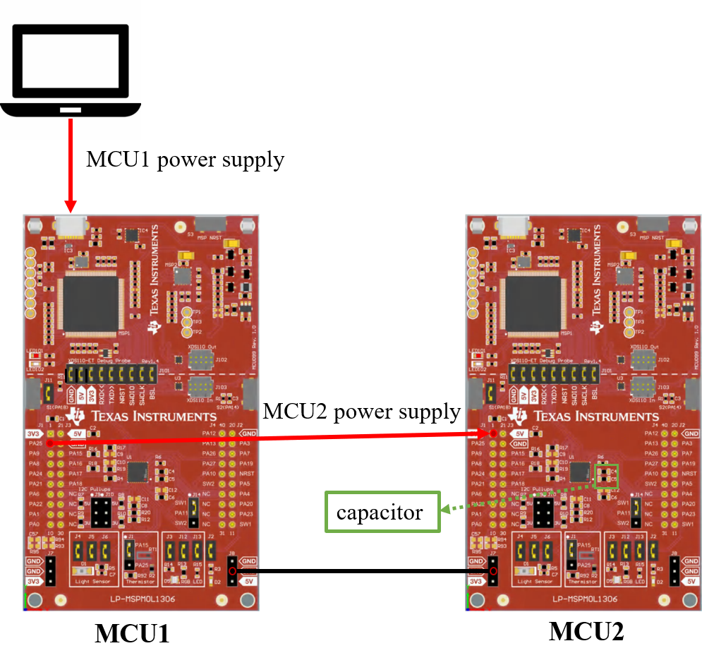
- Connect the MCU1 PA25 and MCU2 3.3V Power pins.
- Co-ground connection.
- Unplug the jumper cap in MCU2.
According to PCB of Launchpad, the C4 and C5(shown in the green box in the Figure 4-2) ,as decoupling capacitors, is connected the ground and VCC. In this way, C4 and C5 meet the connection requirements of the power supply capacitor shown in Figure 4-1. In the following tests, simply change the capacitance sizes of C4 and C5 to simulate different capacitor supply situations.
 Figure 4-2 LP- MSPM0L1306 Hardware Board
Connection
Figure 4-2 LP- MSPM0L1306 Hardware Board
ConnectionFor software set up, MCU2 is running while(1) code in different operation mode.
MCU1 is set up every 2s period to change itsstate through Timer. Besides, another GPIO is toggled at the same time to provide the capacitor charge and discharge start signal.