SLAAEI3 February 2024 MSPM0C1103 , MSPM0C1103-Q1 , MSPM0C1104 , MSPM0C1104-Q1 , MSPM0G1105 , MSPM0G1106 , MSPM0G1107 , MSPM0G1505 , MSPM0G1506 , MSPM0G1507 , MSPM0G3105 , MSPM0G3105-Q1 , MSPM0G3106 , MSPM0G3106-Q1 , MSPM0G3107 , MSPM0G3107-Q1 , MSPM0G3505 , MSPM0G3505-Q1 , MSPM0G3506 , MSPM0G3506-Q1 , MSPM0G3507 , MSPM0G3507-Q1 , MSPM0G3519 , MSPM0L1105 , MSPM0L1106 , MSPM0L1227 , MSPM0L1228 , MSPM0L1228-Q1 , MSPM0L1303 , MSPM0L1304 , MSPM0L1304-Q1 , MSPM0L1305 , MSPM0L1305-Q1 , MSPM0L1306 , MSPM0L1306-Q1 , MSPM0L1343 , MSPM0L1344 , MSPM0L1345 , MSPM0L1346 , MSPM0L2227 , MSPM0L2228 , MSPM0L2228-Q1
4.2 The Result of Experiment
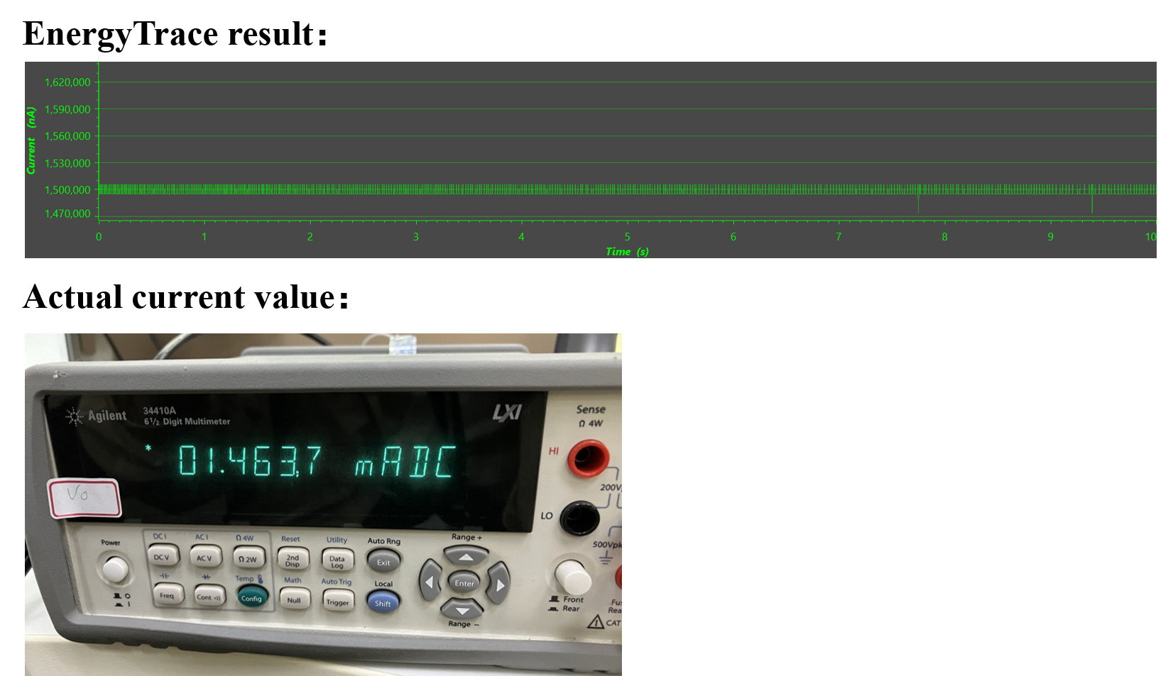
The Figure 4-3 is the experimental result of operating current of MCU run in run0 mode. Both EnergyTrace and direct measurement are all show the run0 current is around 1.5mA.
 Figure 4-3 Operating Current of MCU in run0
Mode
Figure 4-3 Operating Current of MCU in run0
ModeThe power supply of MCU2 was monitored using a logic analyzer and the results are shown in the figure. Channel 1 identifies the GPIO port, and when set to low, MCU1's GPIO is in a high-impedance condition, and MCU2 is powered only by capacitors. Channel 2 is the voltage on both sides of the capacitor, which is the supply voltage of the MCU. As can be seen from the figure, when the voltage drops from 3.3 V to 1.61 V, the duration is about 2.66ms, which is close to the theoretical calculation of 2.56 ms.
 Figure 4-4 The Operating Time of MCU in run0
Mode
Figure 4-4 The Operating Time of MCU in run0
ModeTable 4-1 shows a table summary of the working time of different capacitors in each operating mode.
| Capacitors | STOP0 I=0.32mA | RUN0 I=1.5mA | |||
|---|---|---|---|---|---|
| Type | Capacitance | Measurement Time | Calculation Time | Measurement Time | Calculation Time |
| Tantalum capacitors TAJA225K010RNJ |
2.2μF | 12.01ms | 11.55ms | 2.66ms | 2.56ms |
| Tantalum capacitors TAJA475K010RNJ |
4.7μF | 23.29ms | 24.68ms | 5.10ms | 5.48ms |
| Tantalum capacitors TAJA106K010RNJ |
10μF | 56.72ms | 56.00ms | 12.33ms | 11.67ms |
| Electrolytic capacitors ASLI-D37 |
10μF | 53.79ms | 56.00ms | 11.35ms | 11.67ms |
| Electrolytic capacitors ASLI-E13 |
40μF | 278.95ms | 263.2ms | 57.59ms | 54.33ms |
| Ceramic capacitors GRM21BR61A |
2μF | 12.15ms | 11.2ms | 12.15ms | 11.20ms |
| Ceramic capacitors GRM21BR61A |
4.3μF | 22.76ms | 22.58ms | 4.88ms | 5.02ms |
| Ceramic capacitors GRM21BR61A |
6.3μF | 34.08ms | 33.08ms | 7.30ms | 7.35ms |
As can be seen from the table, the theoretical calculated value is basically consistent with the actual measurement. The reasons for some errors can be: capacitance error value; There is a leakage condition in the meter pen; Cable resistance, energy dissipation, etc. But, the error is within a reasonable range.