SLAU887 February   2023 MSPM0G1105 , MSPM0G1106 , MSPM0G1107 , MSPM0G1505 , MSPM0G1506 , MSPM0G1507 , MSPM0G3105 , MSPM0G3105-Q1 , MSPM0G3106 , MSPM0G3106-Q1 , MSPM0G3107 , MSPM0G3107-Q1 , MSPM0G3505 , MSPM0G3505-Q1 , MSPM0G3506 , MSPM0G3506-Q1 , MSPM0G3507 , MSPM0G3507-Q1 , MSPM0L1105 , MSPM0L1106 , MSPM0L1303 , MSPM0L1304 , MSPM0L1304-Q1 , MSPM0L1305 , MSPM0L1305-Q1 , MSPM0L1306 , MSPM0L1306-Q1 , MSPM0L1343 , MSPM0L1344 , MSPM0L1345 , MSPM0L1346


  1.   Abstract
  2.   Trademarks
  3. 1Overview of BSL Features
  4. 2Terminology
  5. 3BSL Architecture
    1. 3.1 Design
      1. 3.1.1 Timeout Feature
        1. 3.1.1.1 Interface Autodetection
        2. 3.1.1.2 Command Reception
    2. 3.2 BSL Invocation
      1. 3.2.1 Blank Device
      2. 3.2.2 Application Request
      3. 3.2.3 GPIO Based Invocation
      4. 3.2.4 Debug Mailbox Command
      5. 3.2.5 Others
        1. 3.2.5.1 Pre-Boot Application Verification
    3. 3.3 Memory
      1. 3.3.1 SRAM Memory Usage
    4. 3.4 BSL Configuration
    5. 3.5 BSL Status
  6. 4Bootloader Protocol
    1. 4.1 Packet Format
    2. 4.2 UART and I2C BSL Protocol
      1. 4.2.1 BSL Acknowledgment
      2. 4.2.2 Peripheral Configuration
        1. 4.2.2.1 UART
        2. 4.2.2.2 I2C
        3. 4.2.2.3 CRC
    3. 4.3 Bootloader Core Commands
      1. 4.3.1  Connection
      2. 4.3.2  Get Device Info
      3. 4.3.3  Unlock Bootloader
      4. 4.3.4  Program Data
      5. 4.3.5  Program Data Fast
      6. 4.3.6  Readback Data
      7. 4.3.7  Flash Range Erase
      8. 4.3.8  Mass Erase
      9. 4.3.9  Factory Reset
      10. 4.3.10 Standalone Verification
      11. 4.3.11 Start Application
      12. 4.3.12 Change Baud Rate
    4. 4.4 BSL Core Response
      1. 4.4.1 BSL Core Message
      2. 4.4.2 Detailed Error
      3. 4.4.3 Memory Readback
      4. 4.4.4 Device Info
      5. 4.4.5 Standalone Verification
    5. 4.5 Bootloader Security
      1. 4.5.1 Password Protected Commands
        1. 4.5.1.1 Security Alert
      2. 4.5.2 BSL Entry
  7. 5Sample Program Flow with Bootloader
  8. 6Secondary Bootloader
    1. 6.1 Secondary Bootloader Example
  9. 7Interface Plug-in
    1. 7.1 Implementation
      1. 7.1.1 Init
      2. 7.1.2 Receive
      3. 7.1.3 Transmit
      4. 7.1.4 Deinit
      5. 7.1.5 Important Notes
    2. 7.2 Flash Plug-in Type
    3. 7.3 Overriding an Existing Interface
      1. 7.3.1 UART Interface Flash Plug-in Example
  10. 8References
  11. 9Revision History

GPIO Based Invocation

GPIO used for BSL invocation can be configured in the BSL Configuration TRM in Non-main memory.

Fresh devices will have the TI programmed default pin detail in BSL configuration.

GPIO pin based invocation can be disabled in the BCR configuration. It is enabled by default.

GPIO should be asserted before the POR, and the state should be maintained for at-least T_start ms after POR. Then the GPIO pin state can be de-asserted.
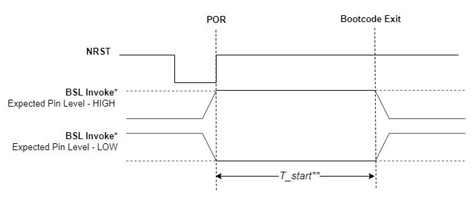
GUID-20221116-SS0I-CZLQ-BHXT-TZ3LWNJV8L8K-low.pngFigure 3-2 Invocation From GPIO

* - GPIO pin to be used as 'BSL Invoke' and 'Expected Pin Level' can be configured in BSL configuration

** - T_start refers to the Cold boot startup time, specified in the device specific data sheet

Note: If pin based BSL invocation is enabled, the configured GPIO pin should be either pulled high or low. It should not be left floating, which could cause unexpected BSL execution.