SLVA505A February 2012 – July 2024 DRV8800 , DRV8801 , DRV8802 , DRV8803 , DRV8804 , DRV8805 , DRV8806 , DRV8811 , DRV8812 , DRV8813 , DRV8814 , DRV8818 , DRV8821 , DRV8823 , DRV8824 , DRV8828 , DRV8829 , DRV8830 , DRV8832 , DRV8832-Q1 , DRV8833 , DRV8834 , DRV8835 , DRV8836 , DRV8837 , DRV8840 , DRV8841 , DRV8842 , DRV8843 , DRV8844 , DRV8870 , DRV8871 , DRV8872
- 1
- Abstract
- Trademarks
- 1Factors Limiting the Maximum Output Current of a Motor Driver
- 2TI Motor Driver OCP Operation
- 3TI Motor Driver Data Sheet Ratings
- 4References
- 5Revision History
1.4.2 Continuous Copper Planes
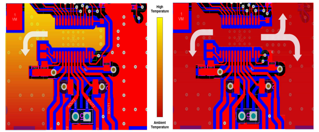
A proper thermal pad connection is critical to provide a low-resistance path to the PCB ground for heat dissipation. These thermal pad connections are made through copper planes that increases the copper area connected to the thermal pad and helps to better dissipate heat. Continuous copper planes make sure effective heat dissipation, preventing overheating and excessive thermal resistance. Interruptions in these planes can lead to higher temperatures both in the device and on the PCB which leads to reduced current carrying capacity.
Connecting the thermal pad to a solid copper plane is crucial for creating a heat exit path from the driver die. To make sure heat flows away from the device, the copper planes must be continuous from the thermal pad to other areas of the board. A best practice is to provide a wide exit path from the copper fill under the driver to a broad, high surface area plane. If these planes are interrupted, the heat exit path becomes constricted, increasing thermal resistance. Higher thermal resistance leads to a greater temperature differential between the thermal pad and the wider surface area on the same plane which can limit motor driver current ratings.
 Figure 1-2 Broken Ground vs Continuous
Ground Pour Heat Map