SNOA930C March 2015 – May 2021 LDC0851 , LDC1001 , LDC1001-Q1 , LDC1041 , LDC1051 , LDC1101 , LDC1312 , LDC1312-Q1 , LDC1314 , LDC1314-Q1 , LDC1612 , LDC1612-Q1 , LDC1614 , LDC1614-Q1 , LDC2112 , LDC2114 , LDC3114 , LDC3114-Q1
2.3.1 Mutual Inductance of Coils in Series
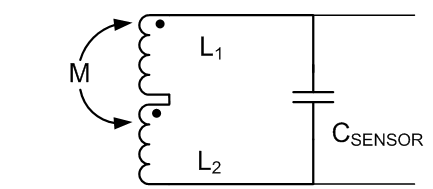
With multi-layer coils aligned as in Figure 2-6, the magnetic fields between each of the layers couple, resulting in an increase in the overall inductance. The equivalent circuit model for a two coil arrangement is shown in Figure 2-8.
 Figure 2-8 Mutual Inductance for Two-Layer Sensor (Ignoring RP)
Because the linkage between the coil fields is positive, the total inductance of the coils in series is:
where
- L1 = inductance of coil 1,
- L2 = inductance of coil 2, which is typical the same as L1 as the geometries are the same, and
- M = mutual inductance between the coils = k × √(L1 ×L2)
The parameter k is a measure of the flux linkage between the coils and varies between 0 and 1, and depends only on the distance between the coils. The mutual inductance is stable and, as shown by Equation 3, increases the total inductance beyond the simple sum of the individual inductances.
In general, for N coils connected in series with positively linked fluxes, the total inductance is given by:

Equation 4 takes into account that there is flux linkage between coils in adjacent layers, plus between coils in alternating layers. Because the degree of mutual inductance between coils is dependent on the separation between layers, the individual mutual inductances vary.
For example, an 18-mm outer diameter, 0.15-mm trace width and trace spacing coil with 12 turns has an inductance of 3.5 µH. If a multi-layer inductor is constructed using of 4 of these single-layer inductors in a 1.0 mm thick PCB, the total inductance is not 4×3.5 µH (14 µH), but is actually 39 µH. The additional 25 µH mutual inductance is actually greater than the 14 µH from the four coils. This mutual inductance has the additional beneficial property of not increasing the sensor RS.
Texas Instruments online WEBENCH® tool supports multi-layer coil design and eliminates the need to employ complex calculations. This can be accessed at http://webench.ti.com/wb5/LDC/#/spirals.