SCAA124 April 2015 RM41L232 , RM42L432 , RM44L520 , RM44L920 , RM46L430 , RM46L440 , RM46L450 , RM46L830 , RM46L840 , RM46L850 , RM46L852 , RM48L530 , RM48L540 , RM48L730 , RM48L740 , RM48L940 , RM48L950 , RM48L952 , RM57L843 , TMS570LC4357 , TMS570LC4357-EP , TMS570LC4357-SEP , TMS570LS0232 , TMS570LS0332 , TMS570LS0432 , TMS570LS0714 , TMS570LS0714-S , TMS570LS0914 , TMS570LS1114 , TMS570LS1115 , TMS570LS1224 , TMS570LS1225 , TMS570LS1227 , TMS570LS2124 , TMS570LS2125 , TMS570LS2134 , TMS570LS2135 , TMS570LS3134 , TMS570LS3135 , TMS570LS3137
1.3 Mitigating Latch-Up
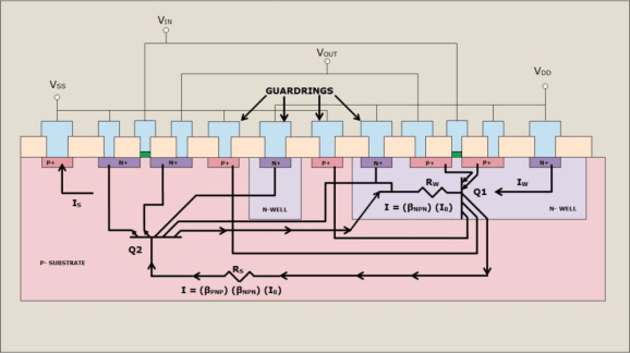
There are methods employed to reduce the possible onset of Latch-Up. Spacing of the elements of each transistor, diode, resistor and capacitor are now being controlled through process characterization and design rules to help minimize the effect of current or voltage pulses on the products. Additionally, guard rings have been added around known radiators in the circuits or if spacing concerns are critical around individual PMOS and NMOS transistors, diodes or substrate resistors. Guard rings act as injected carrier syphons allowing these carriers to flow to the supply or ground. Also, the use of substrate ties and well taps act as excited carrier syphons and are guided by design rules for placement. These ties and taps are necessary for Latch-Up immunity. Another very effective method of quenching Latch-Up is to use an EPI (epitaxial silicon) layer. The EPI layer is doped appropriately for the best transistor performance (more lightly doped than the remaining lower portion of the substrate that is highly doped). The highly doped substrate directs majority carriers to ground and reflects minority carriers making the guard rings more effective (see Figure 3). Even with these safeguards, there is a possibility of parasitic transistors in circuits that are not identified. These unidentified Latch-Up sources need to be identified; one way is a Latch-Up stress test.
 Figure 3. Cross-Section With Guard Rings Included