SLOA285A October 2019 – October 2020 ISO7741 , ISOW7841 , LM25037 , LM25180 , LM5180 , LM5181 , LM5181-Q1 , UCC12040 , UCC12050
4 Open-Loop Push-Pull Topology
A push-pull transformer driver is a popular solution for low-noise, small form factor isolated power supplies. It is supplied from a tightly regulated input rail and operates open loop at a fixed 50% duty cycle. For instance, SN6505 is a low-noise, low-EMI push-pull transformer driver specifically designed for small form factor, isolated power supplies. It drives center-tapped transformer from a DC power supply. Ultra-low noise and EMI are achieved by slew rate control of the output switch voltage and through Spread Spectrum Clocking (SSC). SN6505 includes a soft-start feature that prevents high inrush current during power up with large load capacitors.
 Figure 4-1 Open-Loop Push-Pull Topology Using SN6505
Figure 4-1 shows the schematic for open-loop push-pull topology using SN6505. This topology provides design simplicity by eliminating the feedback loop. The push-pull transformer offers lower primary-secondary capacitance that enables a reduction in common-mode noise compared to Flyback. Additionally, the push-pull topology utilizes the transformer core magnetizing current more efficiently, which results in a smaller magnetic solution compared to the conventional Flyback. The total component count is also very less (close to six excluding the output LDO in Figure 4-1).
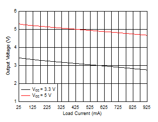
The transformer driver (without any feedback) cannot support a wide input voltage range and instead requires a tightly regulated input voltage. Being an open-loop topology, there is always a concern on output regulation. The typical load regulation for SN6505 is shown in Figure 4-2. Depending on the requirement, an LDO can be used at the output for regulated output.
 Figure 4-2 Output Regulation for SN6505A With Pulse Transformer (Wurth 750315240)