SLVA767A September 2016 – December 2016 SN75469 , TPL7407L , TPL9201 , ULN2003A , ULN2003B , ULN2003V12 , ULN2004A , ULQ2003A , ULQ2003A-Q1 , ULQ2004A , ULQ2004A-Q1
2.2 Bipolar Stepper Motors
Bipolar stepper motors require both a low-side driver and a high-side driver (see Figure 4). This allows the coils to be biased in both directions, requiring two Half-H drivers (one Full-H bridge). The L293D is an example of a device that can drive these types of stepper motors, see Section 3.1 for additional information.
 Figure 4. Variable Low-Side and High-Side Switches/Drivers
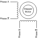
 Bipolar stepper motors only come in a 4-wire configuration and do not have center tap connections. See Figure 5 for the wiring of the bipolar stepper motor.
 Figure 5. 4-Wire Bipolar Stepper Motor