SLYT821 January 2022 AFE0064 , AFE1256 , AFE2256 , AFE3256 , DDC112 , DDC114 , DDC118 , DDC232 , DDC264 , DDC316
4 Final comparison
Table 4-1 summarizes the differences between the two device families.
| DDC Family | AFE Family | |
|---|---|---|
| Number of channels | 2, 4, 8, 16, 32, 64, 128, 256 | 64, 256 |
| Current direction | Into the device | Into or out of the device |
| Bipolar signal integration | No | Yes |
| Input DC voltage | 0 V | Non-zero (1.68 V for the AFE0064) |
| Package | TQFP, small-outline IC, BGA | TQFP, COF |
| Full-scale charge range | 12.5 pC to 350 pC, 1 nC | ≅0.5 pC to >10 pC |
| Maximum full-scale current | 3 µA | 0.5 µA |
| Input referred noise (charge) | 0.2 fCrms (1,250 electrons) | <0.096 fCrms (600 electrons) |
| Input referred noise (current) | 0.5 fArms (at 1 SPS) | <96 fArms (at 1 ms) |
| Maximum sampling rate | ≅5 kSPS | >50 kSPS |
| Maximum integration time | 1 s | 1 ms |
Assume that you want to measure all of the charge produced within 100 ms by each of the 64 photodiodes in an array. Also assume that the maximum current is 1.2 nA. In this case, the maximum charge is 1.2 nA × 100 ms = 120 pC, which the DDC264 could handle in range 3 (150-pC full scale) in a single integration.
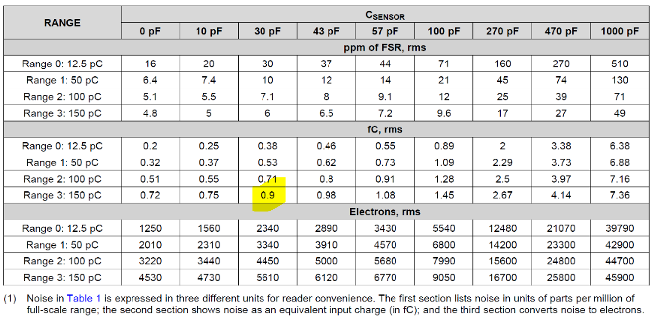
Looking at Figure 4-1 and assuming a 24-pF parasitic detector capacitance, you would expect the noise to be about 0.9 fCrms.
 Figure 4-1 Noise vs
Csensor