SNOA954D November 2019 – June 2021 LDC0851 , LDC1001 , LDC1001-Q1 , LDC1041 , LDC1051 , LDC1101 , LDC1312 , LDC1312-Q1 , LDC1314 , LDC1314-Q1 , LDC1612 , LDC1612-Q1 , LDC1614 , LDC1614-Q1 , LDC2112 , LDC2114 , LDC3114 , LDC3114-Q1
4.1 Inductive Touch Devices
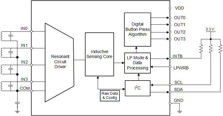
The Mobile Inductive Touch LDC Devices, the LDC3114 as well as the 2-channel LDC2112 and the 4-channel LDC2114, are high-resolution LDCs with internal algorithms optimized for Inductive Touch applications. The internal algorithms extract inductance shifts corresponding to button presses and can report the event through dedicated output pins. A dedicated sensor per channel can detect sensor frequency shifts corresponding to metal deflection smaller than 200 nm. The sensor frequency can go up to 30 MHz, which enables circular buttons as small as 2.4 mm and rectangular buttons smaller than 2.0 mm by 7.0 mm. LDC3114 and LDC2112/4 sensors can be constructed on PCBs or flex PCBs.
 Figure 4-1 LDC3114 Block Diagram
The main features of this family of LDCs include:
- Multiple buttons supported with a single device – up to 4 buttons
- Low Standby current of <5 µA and average operation currents lower than 10 µA
- Wide range of sensor frequencies - from 1 MHz to 30 MHz
- Dedicated output pins to emulate mechanical button operation
- Scan rates of up to 160 SPS
- Supply voltage range of 1.71 V to 1.89 V
- I2C interface for configuration and data readback