-
Demystifying Isolation Certification Standards: Optocouplers vs Opto-emulators SLLA624 October 2023 ISOM8110 , ISOM8110-Q1 , ISOM8111 , ISOM8111-Q1 , ISOM8112 , ISOM8112-Q1 , ISOM8113 , ISOM8113-Q1 , ISOM8115 , ISOM8115-Q1 , ISOM8116 , ISOM8116-Q1 , ISOM8117 , ISOM8117-Q1 , ISOM8118 , ISOM8118-Q1 , ISOM8600 , ISOM8610 , ISOM8710 , ISOM8711
-
Demystifying Isolation Certification Standards: Optocouplers vs Opto-emulators
Demystifying Isolation Certification Standards: Optocouplers vs Opto-emulators
Overview
Traditional optocouplers provide isolation using an LED and a photodiode. LED-based optocouplers are certified according to IEC 60747-5-5, which is the international optocoupler standard that has been active since 2007. Updates to the current (2.0) edition were released in 2020.TI’s new opto-emulators use silicon dioxide (SiO2) isolation technology to provide isolation. As a result, opto-emulators and digital isolators are certified according to a different standard (IEC 60747-17) that became the international digital isolator standard in September 2020.
The new digital isolator standard (IEC 60747-17) has many test requirements that are more stringent and detailed than the optocoupler standard (IEC 60747-5-5). Opto-emulators and digital isolators are evaluated to a criterion that provides a comprehensive understanding of device performance and capability.
IEC 60747-17 versus IEC 60747-5-5 at a glance
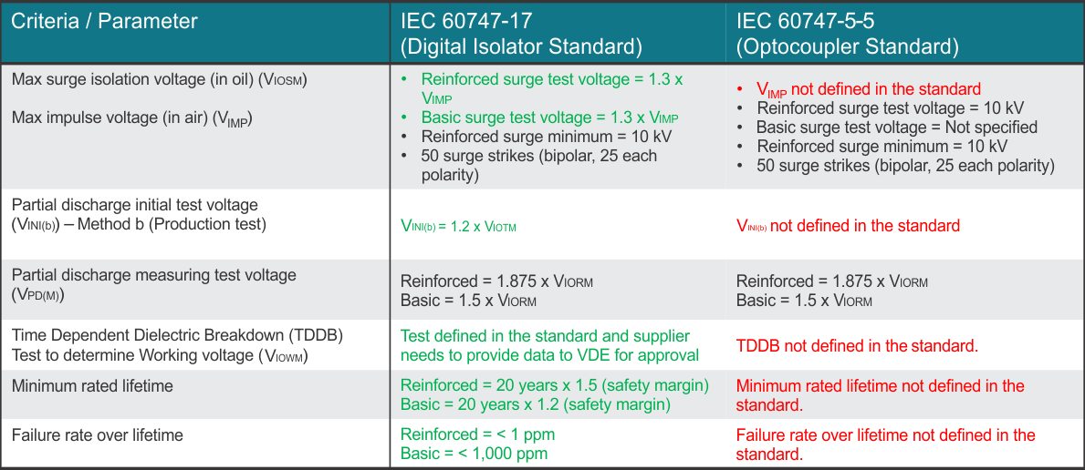
Figure 1 provides an overview comparing the digital isolator standard (IEC 60747-17) and the optocoupler standard (IEC 60747-5-5).For additional information on IEC 607 47-17 specifications, see [FAQ] High-Voltage Isolation Parameters.
 Figure 1 Isolation Standard Comparison
- IEC 60747-17 versus IEC 60747-5-5
Figure 1 Isolation Standard Comparison
- IEC 60747-17 versus IEC 60747-5-5Details
Maximum impulse voltage (VIMP)
To differentiate between isolation performance in oil vs in air, IEC 60747-17 specifies that the isolation performance of a digital isolator is tested in both oil (VIOSM) and in air (VIMP). Whereas the optocoupler standard, IEC 60747-5-5, does not specify both parameters.
When the device is tested in oil, the possibility of arcing across the package is negated. Isolation performance in an application is not accurately represented without also testing in air (VIMP). The digital isolator specification defines VIMP for an in air isolation test and VIOSM for isolation test in oil. Whereas the optocoupler specification only specifies VIOSM and does not specify if the device is tested in air or oil.
When the device is tested in oil, the possibility of arcing across the package is negated. Isolation performance in an application is not accurately represented without also testing in air (VIMP). The digital isolator spec defines VIMP for an in air isolation test and VIOSM for isolation test in oil. The optocoupler specification only specifies VIOSM and does not specify if the device is tested in air or oil.
IEC 60747-17 defines VIMP as a benefit to the customer to understand in system performance of a digital isolator. See the Insulation Specifications section of the data sheet for VIMP and other IEC 60747-17 related specifications, and see [FAQ] What is Maximum Impulse Voltage (VIMP) for more information related to VIMP.
The following sections show the key differences between the two standards:
Partial discharge test (production test): Method B testing
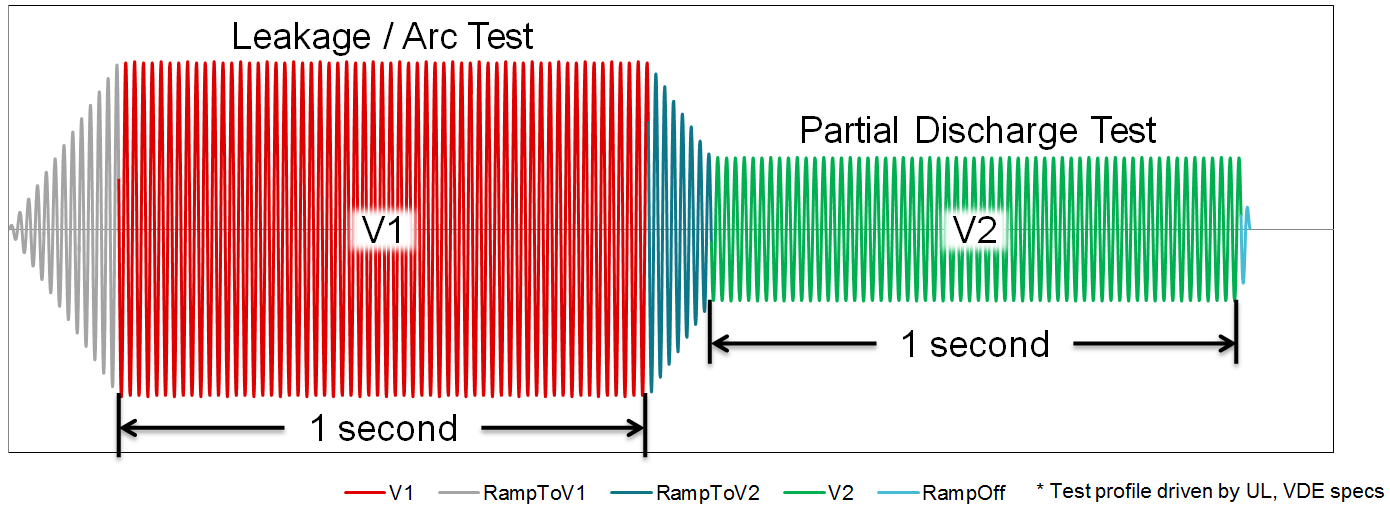
 Figure 2 Method B Test Waveform
Partial Discharge of Digital Isolators and Opto-emulators are testing using the Method b testing. An example of a Method b1 test waveform is shown in Figure 2 which is defined by the IEC 60747-17 standard. Where V1 is the voltage that leakage testing is performed at and V2 is the voltage that partial discharge testing is performed at.
Isolation parameters are tested in production following the method B testing. Digital isolation devices are tested in production using the following procedure.
- One second at 1.2 ×
VIOTM followed by one second at 1.875 × VIORM.
- Optocouplers only specify testing at one second at 1.875 × VIORM.
- For example, for an isolator
rated for 3.75 kVRMS isolation is test at:
- Reinforced isolators are tested at 6.36 kVPK AC 50 Hz and 60 Hz followed by 1.33 kVPK AC 50 or 60 Hz.
- Optocouplers are only required to test at 1.875 × VIORM with no initial stress level voltage (Vini) of one second at 1.2 × VIOTM.
The digital isolator standard contains more stringent test conditions.
Time dependent dielectric breakdown (TDDB) testing
TDDB testing identifies life expectancy associated with the dielectric material of an isolator. TDDB is accelerated by applying an electric field across the dielectric at an increased temperature.
- TI runs TDDB testing across hundreds of units.
- The optocoupler standard does not require TDDB lifetime testing.
For more details on TDDB testing methodology, see Enabling high voltage signal isolation quality and reliability.
Conclusion
Due to rigorous testing through IEC 60747-17, TI has a high confidence in the longevity, robustness, and reliability of the isolation barrier. The additional specifications of IEC 60747-17 also can provide a picture of device performance and insulation capability over IEC 60747-5-5, which is the traditional optocoupler standard.
IMPORTANT NOTICE AND DISCLAIMER
TI PROVIDES TECHNICAL AND RELIABILITY DATA (INCLUDING DATASHEETS), DESIGN RESOURCES (INCLUDING REFERENCE DESIGNS), APPLICATION OR OTHER DESIGN ADVICE, WEB TOOLS, SAFETY INFORMATION, AND OTHER RESOURCES “AS IS” AND WITH ALL FAULTS, AND DISCLAIMS ALL WARRANTIES, EXPRESS AND IMPLIED, INCLUDING WITHOUT LIMITATION ANY IMPLIED WARRANTIES OF MERCHANTABILITY, FITNESS FOR A PARTICULAR PURPOSE OR NON-INFRINGEMENT OF THIRD PARTY INTELLECTUAL PROPERTY RIGHTS.
These resources are intended for skilled developers designing with TI products. You are solely responsible for (1) selecting the appropriate TI products for your application, (2) designing, validating and testing your application, and (3) ensuring your application meets applicable standards, and any other safety, security, or other requirements. These resources are subject to change without notice. TI grants you permission to use these resources only for development of an application that uses the TI products described in the resource. Other reproduction and display of these resources is prohibited. No license is granted to any other TI intellectual property right or to any third party intellectual property right. TI disclaims responsibility for, and you will fully indemnify TI and its representatives against, any claims, damages, costs, losses, and liabilities arising out of your use of these resources.
TI’s products are provided subject to TI’s Terms of Sale (www.ti.com/legal/termsofsale.html) or other applicable terms available either on ti.com or provided in conjunction with such TI products. TI’s provision of these resources does not expand or otherwise alter TI’s applicable warranties or warranty disclaimers for TI products.
Mailing Address: Texas Instruments, Post Office Box 655303, Dallas, Texas 75265
Copyright © 2023, Texas Instruments Incorporated