SLUAAE9B May 2022 – November 2023 TPS62860 , TPS62861 , TPS62864 , TPS62866 , TPS62868 , TPS62869 , TPS62870 , TPS62870-Q1 , TPS62871 , TPS62871-Q1 , TPS62872 , TPS62872-Q1 , TPS62873 , TPS62873-Q1 , TPS62874-Q1 , TPS62875-Q1 , TPS62876-Q1 , TPS62877-Q1 , TPS6287B10 , TPS6287B15 , TPS6287B20 , TPS6287B25 , TPSM8287A06 , TPSM8287A10 , TPSM8287A12 , TPSM8287A15
- 1
- Abstract
- Trademarks
- 1 Introduction
- 2 Smart Routing and Tiny IC Packages
- 3 Selectable Forced-PWM/PSM operation
- 4 Dynamic Output Voltage Adjustment During Operation
- 5 Thermal Considerations
- 6 Droop Compensation
- 7 Step-Down Converter with an I2C Interface Selection Table
- 8 Conclusion
- 9 References
- 10Revision History
3 Selectable Forced-PWM/PSM operation
Battery-powered applications require step-down converters to provide high efficiency numbers at light loads to save power and ensure a long battery run time. Therefore, many step-down converters implement a Power Save Mode (PSM) operation which automatically reduces the switching frequency when in a light load condition. However, this switching frequency reduction increases the output voltage ripple. The higher output voltage ripple magnitude as well as the lower switching frequency may not be acceptable for some sensitive loads.
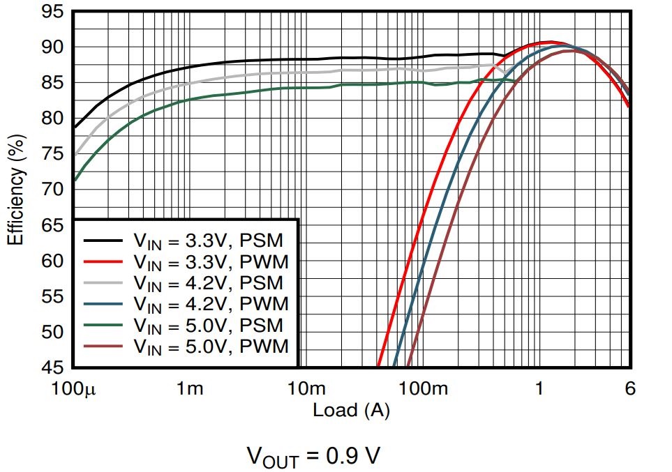
An Enable FPWM Mode bit is available in the Control Register of TPS62866. Enabling this bit forces PWM mode operation to achieve smallest output voltage ripple. Figure 3-2 shows the TPS62866 efficiency curves difference, while Figure 3-2 shows the output-ripple difference. The 4µA IQ of TPS62866 enables high light-load efficiency for many portable applications.
 Figure 3-1 TPS62866 Efficiency Versus Load Current with
Power Save-Mode and Forced PWM Mode
 Figure 3-2 TPS62866 Output Voltage Ripple with Power-Save Mode (left) and Forced PWM Mode (right)
Operating Conditions: VIN=3.3V, Vout=0.9V and Iout= 100 mA