SLOA285A October 2019 – October 2020 ISO7741 , ISOW7841 , LM25037 , LM25180 , LM5180 , LM5181 , LM5181-Q1 , UCC12040 , UCC12050
6 Integrated Isolated Power Solution
The traditional approaches to generate isolated power use a DC/DC converter to drive a transformer in Flyback, Flybuck or push-pull topologies. Pulsating signals on the secondary side are rectified and filtered to generate an isolated DC supply. Opto-coupler-based feedback to the primary side achieves line and load regulation. In certain cases where the DC/DC converter runs in an open-loop configuration, an LDO is used to post-regulate the converter output. The drawback with this discrete approach is that the complete solution – the transformer and other components – occupies a lot of space on the board. Also, designing a stable and efficient isolated power supply can be challenging.
Various latest solutions, integrate a DC/DC converter with a micro-transformer, along with signal-isolation channels, in a single package. Such solutions solve several design challenges faced by system engineers, including:
- Board-area reduction: The first benefit of an integrated solution is a reduction in board area. The solution size reduces significantly since the power stage, transformer, rectifier diodes, isolated feedback (and sometimes, the digital data-isolation channels) are integrated in one single chip. In addition to the surface-area reduction, the use of planar transformers enables the z-dimension or height of the integrated solution to be lower than discrete transformers, which could be two to three times thicker.
- Simplicity and robust design: System design becomes much simpler with an integrated solution, since user can integrate the feedback for line/load regulation and all protection mechanisms for the power supply (such as overload and short-circuit protection, thermal shutdown and soft start) on the chip. Boards with bulky transformers perform poorly in vibration tests. Thus, board-level reliability can also improve with an integrated solution.
The Texas Instruments UCC12050 is part of a family of reinforced isolated DC/DC bias converters and modules. It integrates a transformer and DC/DC controller with a proprietary architecture to achieve high efficiency with very low emissions. It provides 500 mW (typical) of isolated output power at peak efficiency of 60%. The UCC12050 device is suitable for applications that have limited board space and desire more integration.
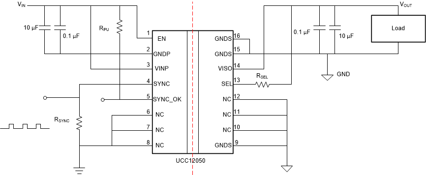
UCC12050 integrates a highly innovative transformer to enable a package size of 10.3 x 10.3 mm with only 2.65 mm height. The integrated thermal shutdown and tolerance to short-circuit at the output enables very robust applications. This device is also suitable for modules where transformers meeting the required isolation specifications are bulky and expensive. Figure 6-1 shows an example schematic.
 Figure 6-1 UCC12050 Schematic Showing Low Component Count
Compared to similar competition products in this category, UCC12050 provides almost 30% higher efficiency, 30°C lower temperature rise at full load and can pass CISPR 32 Class B emissions testing on a two-layer PCB without LDOs or ferrite beads (see Figure 6-2). In an apples-to-apples comparison with competition UCC12050 has over 20dB of emissions improvement.
 Figure 6-2 UCC12050 Shows Lower Radiated Emissions Than Competitive Integrated Device