SPRADJ8 October 2024 AM3351 , AM3352 , AM3354 , AM3356 , AM3357 , AM3358 , AM3359 , AM4372 , AM4376 , AM4377 , AM4378 , AM4379 , AM620-Q1 , AM623 , AM625 , AM625-Q1 , AM62A1-Q1 , AM62A3 , AM62A3-Q1 , AM62A7 , AM62A7-Q1 , AM62P , AM6411 , AM6412 , AM6421 , AM6422 , AM6441 , AM6442 , DP83822H , DP83822HF , DP83822I , DP83822IF , DP83826E , DP83826I , DP83848-EP , DP83848Q-Q1 , DP83867CR , DP83867CS , DP83867E , DP83867IR , DP83867IS , DP83TC812R-Q1 , DP83TC812S-Q1 , DP83TC813R-Q1 , DP83TC813S-Q1 , DP83TC814R-Q1 , DP83TC814S-Q1 , DP83TG720R-Q1 , DP83TG720S-Q1 , DP83TG721R-Q1 , DP83TG721S-Q1
- 1
- Abstract
- Trademarks
- 1 Terminology
- 2 Prerequisites
- 3 Quick Initial Steps
- 4 Debug Overview
- 5 Network Driver Initialization Process
- 6 Ethernet PHY Analysis
- 7 Ethernet MAC Statistics Analysis
- 8 How IPv4 Address is Obtained
- 9 Follow the Packet
- 10Debug Network Topologies and Techniques
- 11Linux® Utilities Summary
- 12Checklist for Requesting Ethernet Support
6 Ethernet PHY Analysis
This section covers some basic Ethernet PHY debug steps to make sure that the PHY has initialized and is operating correctly.
The first area to examine are the power supply and clock out signals of the Ethernet PHY. If possible, look for a troubleshooting guide from the Ethernet PHY vendor. For example, the DP83869 Ethernet PHY from TI has a troubleshooting guide that demonstrates how to do basic evaluation of the DP83869 PHY.
For discussion purposes, the DP83869 Troubleshooting Guide is used as an example on basic Ethernet PHY voltage and clocking debug.
There are some peripheral pins on the Ethernet PHY to pay close attention to. As a reference, these pins are specified in the peripheral pin checks section of the referenced troubleshooting guide. The referenced troubleshooting guide contains significantly more details.
- Power Supplies
- Verify each voltage rail is within tolerance specified by the Ethernet PHY data sheet of the manufacturer
- Probe the XI Clock
- The input clock is necessary for the PHY to be operational
- Confirm the signal is present and meets the specifications of the PHY
- Probe the RESET_N Signal
- Verify the PHY is not being held in reset
- Probe the Strap Pins During
Initialization
- This is how the PHY finds
the configuration
- Example: the PHY address on the MDIO bus is one of the configurations
- The troubleshooting guide suggests a specific debug technique to follow
- See also, the How to Confirm Ethernet PHY Strapping TI E2E™ FAQ
- This is how the PHY finds
the configuration
- Probe the Serial Management
Interface Signal (MDC, MDIO)
- Reference the expected resistive tolerances and signal integrity requirements from the PHY data sheet
- This step is not
necessary if the PHY registers are accessible through the
ethtoolutility (for example,ethtool eth0)
If the peripheral pins are
verified to be correct and the MDIO bus is correctly signaling; however,
communication is not happening with the PHY, the next debug step is to check the
MDIO driver and the selected PHY driver. Analyzing the MDIO driver and communication
is covered in Section 5. An additional
reference is in the dmesg | grep -i mdio section
of the How to Integrate Linux Driver application note which covers
an MDIO interaction example.
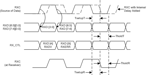
Pay particular attention to the MAC - PHY interface when in RGMII mode. The key debug element here is that RX clock from the PHY to the MAC needs to be delayed relative to the RX data. If this timing is not correct, this causes issues with the reception of Ethernet frames. Errors such as dropped frames or RX CRC errors are measured at the MAC. TI Arm® based processor MACs automatically apply a 2ns delay on the TX clock relative to the TX data when operating in the RGMII interface mode. An additional note is that board layout and trace length of the clock and data lines are critical to defining the correct clock delay. The High-Speed Interface Layout Guidelines application note provides information on the importance of high-speed layout.
The board DTS defines the RX clocking delay information to be used by the PHY driver. See the How to Integrate Linux Driver application note for an example on how the RX clocking delay is configured.
The following snippet is a DTS example of how the RX clocking delay is configured.
(Linux Source tree directory) arch/arm64/boot/dts/ti/k3-am62x-sk-common.dtsi (a portion from this file)

#include <dt-bindings/net/ti-dp83867.h> <-- Has the macro defines used in the phy node

cpsw3g_phy0: ethernet-phy@0 {
bootph-all;
	reg = <0>;
	ti,rx-internal-delay = <DP83867_RGMIIDCTL_2_00_NS>; <-- rx clock delay
	ti,fifo-depth = <DP83867_PHYCR_FIFO_DEPTH_4_B_NIB>;
	ti,min-output-impedance;
};
An example of the required RX clock delay here is referenced from the DP83869 Ethernet PHY data sheet that defines the necessary RX clock delay.
 Figure 6-1 RGMII Receive Multiplexing and
Timing Diagram
Figure 6-1 RGMII Receive Multiplexing and
Timing DiagramSection Summary:
How to verify if the Ethernet PHY is operating
- Verify the peripheral pins are either operating as expected and within tolerances specified by the PHY data sheet and the troubleshooting guide for the PHY if one exists
- Review that the MDIO driver has initialized without errors and has identified all the expected PHYs in the Linux console log.
- If the PHY interface is RGMII, check that the RX clock is delayed per the board layout and verify the RX clock delay is configured correctly in the board DTS file.