How to Pass IEEE Ethernet Compliance Tests
Trademarks
E2E is a trademark of Texas Instruments.
Microsoft are registered trademarks of Microsoft Corporation.
Tektronix is a registered trademark of Tektronix, Inc..
All trademarks are the property of their respective owners.
1 Introduction
Why is IEEE Ethernet Compliance testing important?
The IEEE 802.3 standard defines a set of compliance tests for the 1000BASE-T Ethernet physical layer. These tests are intended to ensure reliable communications over an Ethernet network. To perform this testing, the device under test (DUT) is placed in each of four IEEE 802.3 specified modes. The standard defines the test modes as listed in Table 1-1.
| Test Mode | Test | IEEE 802.3 Reference |
|---|---|---|
| Test Mode-1 | Peak Droop Template |
40.6.1.2.1 40.6.1.2.2 40.6.1.2.3 |
| Test Mode-2 Test Mode-3 |
Transmitter Jitter Receiver Jitter |
40.6.1.2.5 |
| Test Mode-4 | Distortion MDI Return Loss MDI Common Mode Voltage |
40.6.1.2.4 40.8.3.1 40.8.3.3 |
Ethernet compliance is executed with an oscilloscope that operates a specific Ethernet compliance software test suite. Such Ethernet compliance test equipment is made available for purchase from many test equipment manufacturers like Tektronix, Agilent, Lecroy and others.
Problem Description
Ethernet compliance test equipment implements a software test suite. The software suite executes the test cases step by step in a semi-automated way. The IEEE specification in some cases does not provide a fixed formula but describes the type of math in text form. Each test equipment vendor has the freedom to implement their own measurement ways and formulas. As result, different interpretations of the math formula have been implemented by manufacturers in their Ethernet compliance testing software suite.
Specifically, we are looking at test case “Peak differential output voltage and level accuracy” as described in IEEE 802.3-2018 Subclause 40.6.1.2.1. This test case requires Test Mode-1 to be activated in the Ethernet PHY.
What we have observed in the market is that two different kinds of formulas are implemented by test tool manufacturers. One formula calculates percentage error, while the other calculates percentage difference.
Some manufacturers implemented the percentage error formula in a different way to other manufacturers. In some cases, this resulted in a doubling of test values, and subsequently erroneous failures. Figure 1-1 illustrates an example.

Figure 1-1 Peak A vs Peak B Failure due to Incorrect Formula
Figure 1-1 uses the wrong formula and therefore fails to pass Peak A versus Peak B test case. In some cases, the Ethernet compliance test vendors have already updated their Ethernet compliance test suite firmware with the corrected formula. The engineer performing Ethernet compliance test cases may need to update the test equipment software with the latest software version from the manufacturer. For the update the vendor of the test equipment has to be contacted.
Contact the test equipment vendor for updates. Use this application note to determine whether or not the correct formula for the Peak A versus Peak B test is used by the test equipment.
2 IEEE Specification and How to Derive the Formula
The IEEE 802.3-2018, Subclause 40.6.1.2.1 is written as follows:
-
"The absolute value of the peak of the waveform at points A and B, as
defined in Figure 40–20, shall fall within the range of 0.67 V to 0.82 V
(0.75 V ± 0.83 dB). These measurements are to be made for each pair while
operating in test mode 1 and observing the differential signal output at the
MDI using transmitter test fixture 1 with no intervening cable.
The absolute value of the peak of the waveforms at points A and B shall
differ by less than 1% from the average of the absolute values of the peaks
of the waveform at points A and B.
The absolute value of the peak of the waveform at points C and D as defined
in Figure 40–20 shall differ by less than 2% from 0.5 times the
average of the absolute values of the peaks of the waveform at points
A and B."
See Figure 40–20—Example of transmitter test mode 1 waveform (1 cycle) in the IEEE specification for further explanation of the points A and B:
The second paragraph of the specification description in section 40.6.1.2.1 contains the description of the math formula required to calculate “Peak A vs. Peak B”: The absolute value of the peak of the waveforms at point A and B shall differ by less than 1% from the average of the absolute value of the peaks of the waveform at point A and B.
The first part of the sentence “the absolute value of the peak of waveforms at point A and B” means that each of them individual waveforms need to comply to the next part of the sentence. It also means that signs of the measurement values have to be removed and the absolute value must be used.
The second part of the sentence “… average of the peaks of the waveforms at point A and B” refers to the following percentage error formula.
The percentage error formula is defined as follows:
-
Percent Error
Applied when comparing an experimental quantity, with a theoretical
quantity, which is considered the “correct” value. The percent error is the
absolute value of the difference divided by the “correct” value times
100.
E is the measured value, either Peak A or Peak B.
The theoretical quantity T is defined as the average of Va and Vb, which is calculated as:
When Peak A absolute value is Va and Peak B absolute value is Vb, the following formula of the IEEE specification and the percent error formula can be derived:
3 Formula Helper to Calculate Limit
The following formula can be copied into a Microsoft® Excel file. With this helper the engineer can validate if the test equipment vendor is using the correct percent error formula:
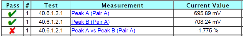
Va = 695.89 mV
Vb = 708.24 mV
=100*((B2-0.5*(B1+B2))/(0.5*(B1+B2)))

Figure 3-1 Formula in Microsoft® Excel
The result in the Excel table cell B3 reports that the test result has been passed because it is below 1%. The test report from the test equipment vendor shows a failed test case. In this case the formula used in Figure 1-1 by the manufacturer is incorrect and out-of-date. When facing this situation, contact the test manufacturer for a software update.
4 Conclusion and Summary
This application brief provides a simple and easy method to validate if the test case passes even though the test report shows a test case failure. When the test case fails after validating the formula, further hardware analysis must be made to find the root cause of the failure. From TI experience the following can cause the Ethernet compliance test case to fail:
- Incorrect formula - check that the formula for the test case is correct using the formula and method described in Section 3.
- Unsupported transformer - Validate that the transformer used in the design does match with the Ethernet PHYs transformer requirements (see the transformer section in the data sheet and compare it with transformer data sheet and schematics implementation).
- Layout optimization - Review the Ethernet PHY layout guidelines and recommendations in the PHY data sheet.
- Transmission line interaction - Cross talk impact of transmission lines by enabling transmit on signal pair only.
- Drive strength tuning - Some Ethernet PHYs have the capabilities to increase or decrease the transmission drive strength on the MDI interface inside the PHY. Tuning the drive strength per pair can be used to potentially pass the compliance tests.
- Magnetics decoupling - On the MDI side, capacitors are connected to the center taps of the transformer. Tuning the value of these capacitors may help pass the compliance tests.
Additional components on the MDI routing to Magentics: ESD or other components with high capacitance and impedance added on the path will be evaluated.
Post Ethernet questions to the TI E2E™ forum.