SLLA284G July 2022 – September 2023 ISO5451 , ISO5452 , ISO5851 , ISO5852S , ISO7142CC , ISO7142CC-Q1 , ISO721 , ISO721-Q1 , ISO721M , ISO721M-EP , ISO722 , ISO7220A , ISO7220M , ISO7221A , ISO7221B , ISO7221C , ISO7221M , ISO722M , ISO7230C , ISO7230M , ISO7231C , ISO7231M , ISO7240C , ISO7240CF , ISO7240M , ISO7241C , ISO7241M , ISO7242C , ISO7242M , ISO7310-Q1 , ISO7310C , ISO7340-Q1 , ISO7340C , ISO7340FC , ISO7341-Q1 , ISO7341C , ISO7341FC , ISO7342-Q1 , ISO7342C , ISO7342FC , ISO7740 , ISO7741 , ISO7742 , ISO7760 , ISO7761 , ISO7762 , ISO7810 , ISO7820 , ISO7821 , ISO7830 , ISO7831 , ISO7840 , ISO7841 , ISO7842
1.2 On-Off Keying (OOK) Based Communication
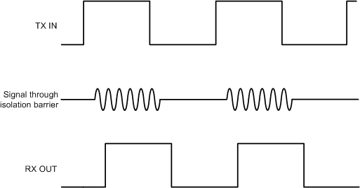
The conceptual operation of OOK-based communication is shown in Figure 1-2. The corresponding signaling is shown in Figure 1-3. The isolators in the ISO67xx, ISO78xx and ISO77xx family use this architecture.
In this architecture, the incoming digital bit stream is modulated with an internal spread spectrum oscillator clock to generate OOK signaling, such that one of the input states is represented by transmission of a carrier frequency, and the other state by no transmission. This modulated signal is coupled to the isolation barrier and appears in an attenuated form on the receive side. The receive path consists of a pre-amplifier to gain up the incoming signal followed by an envelope detector that serves as a demodulator to regenerate the original digital pattern. The TX and RX signal conditioning circuits are used to improve the common mode rejection of the channel resulting in better Common Mode Transient Immunity (CMTI).
 Figure 1-2 Conceptual Block Diagram of On-Off Keying (OOK) Architecture
 Figure 1-3 Representative Signal in OOK Architecture