SBAA274A September   2018  – March 2023 ADS1118 , ADS1119 , ADS1120 , ADS112C04 , ADS112U04 , ADS1146 , ADS1147 , ADS1148 , ADS114S06 , ADS114S06B , ADS114S08 , ADS114S08B , ADS1219 , ADS1220 , ADS122C04 , ADS122U04 , ADS1246 , ADS1247 , ADS1248 , ADS124S06 , ADS124S08 , ADS125H02 , ADS1260 , ADS1261 , ADS1262 , ADS1263


  1.   A Basic Guide to Thermocouple Measurements
  2.   Trademarks
  3. 1Thermocouple Overview
    1. 1.1 Seebeck Voltage
    2. 1.2 Thermocouple Types
      1. 1.2.1 Common Thermocouple Metals
      2. 1.2.2 Thermocouple Measurement Sensitivity
        1. 1.2.2.1 Calculating Thermoelectric Voltage from Temperature
        2. 1.2.2.2 Calculating Temperature From Thermoelectric Voltage
      3. 1.2.3 Thermocouple Construction
      4. 1.2.4 Tolerance Standards
    3. 1.3 Thermocouple Measurement and Cold-Junction Compensation (CJC)
    4. 1.4 Design Notes
      1. 1.4.1 Identify the Range of Thermocouple Operation
      2. 1.4.2 Biasing the Thermocouple
      3. 1.4.3 Thermocouple Voltage Measurement
      4. 1.4.4 Cold-Junction Compensation
      5. 1.4.5 Conversion to Temperature
      6. 1.4.6 Burn-out Detection
  4. 2Thermocouple Measurement Circuits
    1. 2.1 Thermocouple Measurement With Pullup and Pulldown Bias Resistors
      1. 2.1.1 Schematic
      2. 2.1.2 Pros and Cons
      3. 2.1.3 Design Notes
      4. 2.1.4 Measurement Conversion
      5. 2.1.5 Generic Register Settings
    2. 2.2 Thermocouple Measurement With Biasing Resistors Attached to the Negative Lead
      1. 2.2.1 Schematic
      2. 2.2.2 Pros and Cons
      3. 2.2.3 Design Notes
      4. 2.2.4 Measurement Conversion
      5. 2.2.5 Generic Register Settings
    3. 2.3 Thermocouple Measurement With VBIAS for Sensor Biasing and Pullup Resistor
      1. 2.3.1 Schematic
      2. 2.3.2 Pros and Cons
      3. 2.3.3 Design Notes
      4. 2.3.4 Measurement Conversion
      5. 2.3.5 Generic Register Settings
    4. 2.4 Thermocouple Measurement With VBIAS For Sensor Biasing and BOCS
      1. 2.4.1 Schematic
      2. 2.4.2 Pros and Cons
      3. 2.4.3 Design Notes
      4. 2.4.4 Measurement Conversion
      5. 2.4.5 Generic Register Settings
    5. 2.5 Thermocouple Measurement With REFOUT Biasing and Pullup Resistor
      1. 2.5.1 Schematic
      2. 2.5.2 Pros and Cons
      3. 2.5.3 Design Notes
      4. 2.5.4 Measurement Conversion
      5. 2.5.5 Generic Register Settings
    6. 2.6 Thermocouple Measurement With REFOUT Biasing and BOCS
      1. 2.6.1 Schematic
      2. 2.6.2 Pros and Cons
      3. 2.6.3 Design Notes
      4. 2.6.4 Measurement Conversion
      5. 2.6.5 Generic Register Settings
    7. 2.7 Thermocouple Measurement With Bipolar Supplies And Ground Biasing
      1. 2.7.1 Schematic
      2. 2.7.2 Pros and Cons
      3. 2.7.3 Design Notes
      4. 2.7.4 Measurement Conversion
      5. 2.7.5 Generic Register Settings
    8. 2.8 Cold-Junction Compensation Circuits
      1. 2.8.1 RTD Cold-Junction Compensation
        1. 2.8.1.1 Schematic
          1. 2.8.1.1.1 Design Notes
          2. 2.8.1.1.2 Measurement Conversion
          3. 2.8.1.1.3 Generic Register Settings
      2. 2.8.2 Thermistor Cold-Junction Compensation
        1. 2.8.2.1 Schematic
        2. 2.8.2.2 Design Notes
        3. 2.8.2.3 Measurement Conversion
        4. 2.8.2.4 Generic Register Settings
      3. 2.8.3 Temperature Sensor Cold-Junction Compensation
        1. 2.8.3.1 Schematic
        2. 2.8.3.2 Design Notes
        3. 2.8.3.3 Measurement Conversion
        4. 2.8.3.4 Generic Register Settings
  5. 3Summary
  6. 4Revision History

Schematic

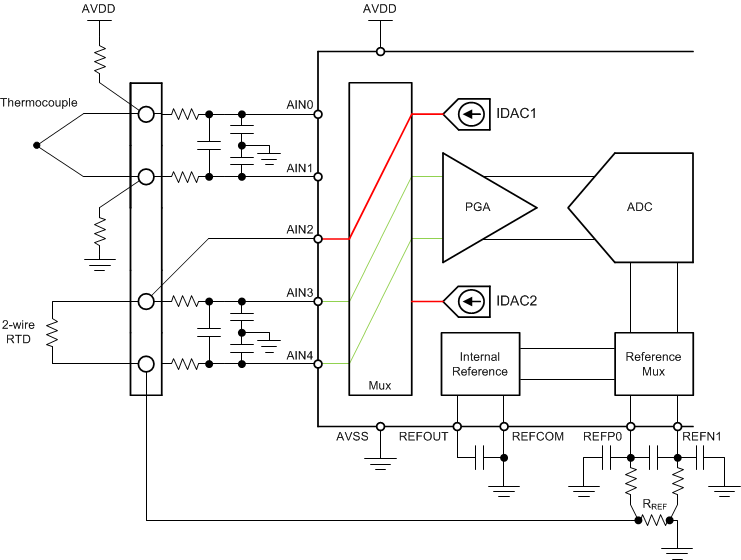
GUID-293023C2-74E4-47AF-BDB0-2770710F73B3-low.gifFigure 2-8 Thermocouple Measurement Circuit With Two-Wire RTD Cold-Junction Compensation