SLPA021 November 2024 CSD13303W1015 , CSD16301Q2 , CSD16321Q5 , CSD16322Q5 , CSD16323Q3 , CSD16325Q5 , CSD16327Q3 , CSD16340Q3 , CSD16342Q5A , CSD16401Q5 , CSD16403Q5A , CSD16404Q5A , CSD16406Q3 , CSD16407Q5 , CSD16408Q5 , CSD16409Q3 , CSD16410Q5A , CSD16411Q3 , CSD16412Q5A , CSD16413Q5A , CSD16414Q5 , CSD16415Q5 , CSD16556Q5B , CSD17301Q5A , CSD17302Q5A , CSD17303Q5 , CSD17304Q3 , CSD17305Q5A , CSD17306Q5A , CSD17307Q5A , CSD17308Q3 , CSD17309Q3 , CSD17310Q5A , CSD17311Q5 , CSD17312Q5 , CSD17313Q2 , CSD17322Q5A , CSD17327Q5A , CSD17381F4 , CSD17501Q5A , CSD17505Q5A , CSD17506Q5A , CSD17507Q5A , CSD17510Q5A , CSD17522Q5A , CSD17527Q5A , CSD17551Q3A , CSD17551Q5A , CSD17552Q3A , CSD17552Q5A , CSD17553Q5A , CSD17555Q5A , CSD17556Q5B , CSD17559Q5 , CSD18501Q5A , CSD18502KCS , CSD18502Q5B , CSD18503KCS , CSD18503Q5A , CSD18504KCS , CSD18504Q5A , CSD18531Q5A , CSD18532KCS , CSD18532NQ5B , CSD18532Q5B , CSD18533KCS , CSD18533Q5A , CSD18534KCS , CSD18534Q5A , CSD18537NKCS , CSD18537NQ5A , CSD18563Q5A , CSD22202W15 , CSD25211W1015 , CSD25213W10 , CSD75207W15 , CSD86311W1723 , CSD86330Q3D , CSD86350Q5D , CSD86360Q5D , CSD87312Q3E , CSD87330Q3D , CSD87331Q3D , CSD87350Q5D , CSD87351Q5D , CSD87351ZQ5D , CSD87352Q5D , CSD87353Q5D , CSD87381P , CSD87588N
3 Application-specific FETs
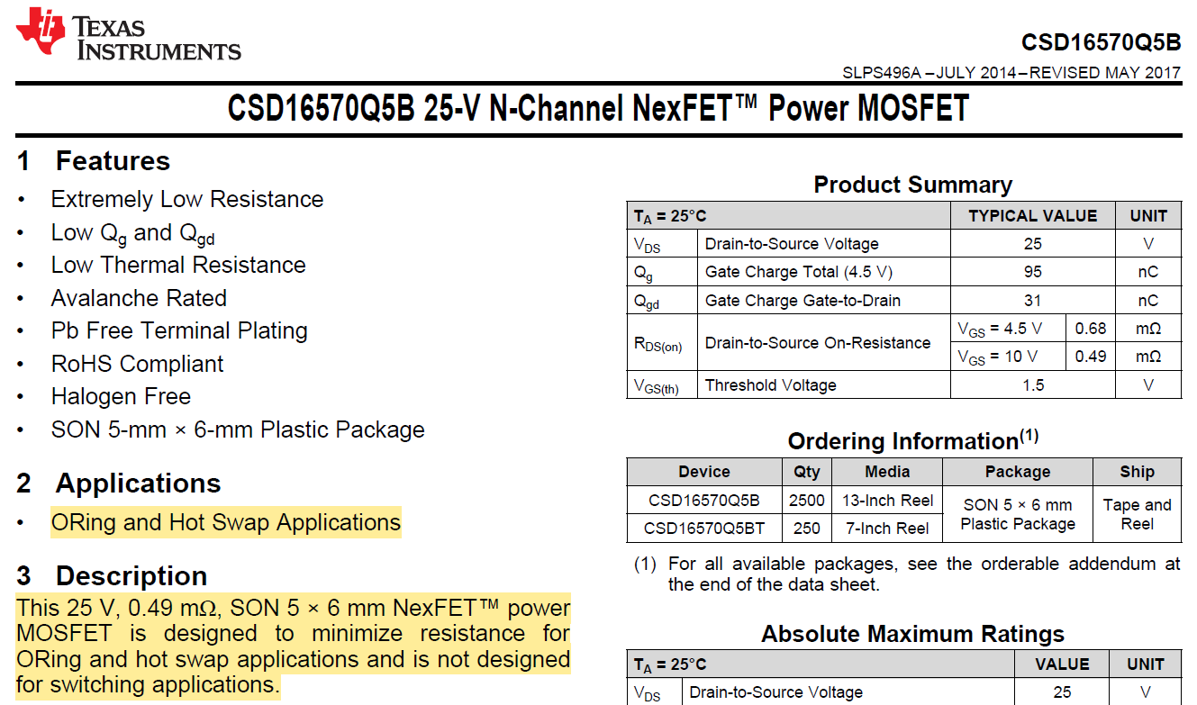
Some FETs are optimized for switch-mode applications while others are better suited for static switching. Some can work in either application type. The first thing to do is review the FET data sheet. On page 1, TI FET data sheets include information on applications the FET is optimized for. For example, Figure 3-1 shows the CSD16570Q5B data sheet and this FET is optimized for ORing and hot swap applications.
 Figure 3-1 CSD16570Q5B Data Sheet
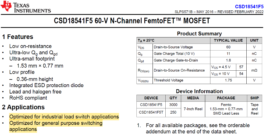
Likewise, Figure 3-2 shows an excerpt from the CSD18541F5 data sheet. This device is optimized for load switch and general purpose switching applications.
 Figure 3-2 CSD18541F5 Data Sheet
Digging further into the data sheet dynamic characteristics, the CSD16570Q5B is not a good candidate for switch-mode applications as the charge ratio, Qgd/Qgs > 1. This makes the MOSFET more susceptible to CdV/dt induced turn-on when used as the low side FET in a synchronous buck converter. Similarly, the CSD18541F5 has a charge ratio > 1, but the typical internal series gate resistance is RG = 1200Ω. This limits the switching speed and this FET is not the best for switch-mode applications. If there are some questions whether a FET can be used in a particular application, then review the Applications section and Dynamic Characteristics section in the data sheet. If there are further questions, then contact your FET vendor for more information.