SNVA856B May 2020 – October 2022 LM63615-Q1 , LM63625-Q1 , LM63635-Q1 , LMR33620 , LMR33620-Q1 , LMR33630 , LMR33630-Q1 , LMR33640 , LMR36006 , LMR36015 , TPS54360B , TPS54560B
- Working With Inverting Buck-Boost Converters
- Trademarks
- 1 Introduction
- 2 Inverting Buck-Boost Converter
- 3 Basic Operation
- 4 Operating Considerations of a Buck Based Inverting Buck-Boost
- 5 Component Selection for the IBB
- 6 General Considerations
- 7 Auxiliary Functions
- 8 Design Examples
- 9 Summary
- 10References
- 11Revision History
4.4.3 Simulation
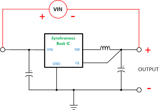
Simulating an IBB can be tricky. Typically, you can't take a simulation model for a buck and use it directly for an IBB. This is because the internal circuits in the model are referenced to a global "ground", or zero volt reference node. As we have seen, for the IBB topology, the IC ground becomes the output voltage in the application. There are two ways to get around this issue. In many cases, you will find a dedicated IBB model on the product folder for the device you are interested in. Usually the file name will contain wording such as "inverting", or "IBB". These are the same models as for the buck regulator, but with the ground of the internal circuits separated from the zero volt reference. These models can be used directly to simulate an IBB. Where a dedicated IBB model is not available, the trick shown in Figure 4-4 can be used. With this method, the input supply is boot-strapped across the input and output of the buck converter. In this case you must be careful when monitoring voltages to ensure that you have the correct reference point for the measurement.
 Figure 4-4 Simulation of IBB