DLPA059H January 2015 – April 2024 DLP160AP , DLP160CP , DLP2000 , DLP2010 , DLP230NP , DLP3010 , DLP3310 , DLP470NE , DLP470TE , DLP4710 , DLP471NE , DLP471TE , DLP471TP , DLP472NE , DLP472TE , DLP480RE , DLP550HE , DLP550JE , DLP650LE , DLP650NE , DLP650TE , DLP651LE , DLP651NE , DLP660TE , DLP670RE , DLP780NE , DLP780TE , DLP781NE , DLP781TE , DLP800RE , DLP801RE , DLP801XE , DLPA1000 , DLPA2000 , DLPA2005 , DLPA3000 , DLPA3005 , DLPC2607 , DLPC3420 , DLPC3421 , DLPC3430 , DLPC3433 , DLPC3435 , DLPC3438 , DLPC3439 , DLPC6401 , DLPC6540
This application note is a comprehensive quick guide to find important resources for DLP® display products intended for industrial, enterprise, or personal electronics applications. This document serves as a starting guide for DLP chipset selection, evaluation, design, and manufacturing. You can benefit from this document regardless of your experience level and involvement with a DLP display system. You can send feedback or comments on this document using TI DLP Products E2E support forum.
The maturity of the design and manufacturing ecosystem for DLP display technology allows developers to take display application concepts to production quickly as illustrated below.
Interested in DLP technology outside of industrial, enterprise, and personal electronics display applications? Click here for DLP automotive applications and click here for Light Control applications using DLP technology, such as 3D print, 3D machine vision, and 3D scanning.
LightCrafter™, DLP IntelliBright™, and DLP Composer™ are trademarks of Texas Instruments.
DLP® is a registered trademark of Texas Instruments.
All trademarks are the property of their respective owners.
DLP® display products are used in a wide range of traditional accessory projectors and emerging display equipment. These include embedded projectors in smart phones and tablets, interactive surface computing, screenless and laser TVs, augmented reality glasses, digital signage, projection mapping, large venue, and cinema. DLP display technology contains two families of products, DLP Pico™ chipsets and DLP Standard chipsets. DLP Pico chipsets offer versatile display capability and can create images on virtually any surface from ultramobile devices. They are a good fit for any application requiring a display with high contrast, small size, and low power. DLP Standard chipsets enable amazing images for systems that require large screen bright displays with high resolution.
To help you navigate through this document, a Table 1-1 is provided to assist in prioritizing the sections that you might be interested in.
I am... | Electrical Engineer | Optical Engineer | Software Engineer | Systems Engineer | Portfolio Manager |
---|---|---|---|---|---|
New to DLP technology | |||||
Selecting a DLP chipset | |||||
Evaluating a DLP chipset | |||||
Development and Manufacturing |
As you move along with your display application development, see the Table 1-1. For a quick reference guide on DLP Pico technology, see Getting Started with DLP Pico technology.
Table 2-1 shows the main benefits that DLP projection enables for virtually any display application.
Benefit | Description | |
---|---|---|
Excellent image quality | Based on the same display technology used in 9 out of 10 cinemas worldwide (Based on PMA Research), the DLP chipset can enable a display that offers saturated colors and high contrast. Display system performance can vary depending on the optical engine. | |
Highcontrast ratio | The reflective technology of DLP technology allows for high contrast as off state mirrors reflect light away from the projection optics creating very black pixels on the display surface. | |
Free form display | 
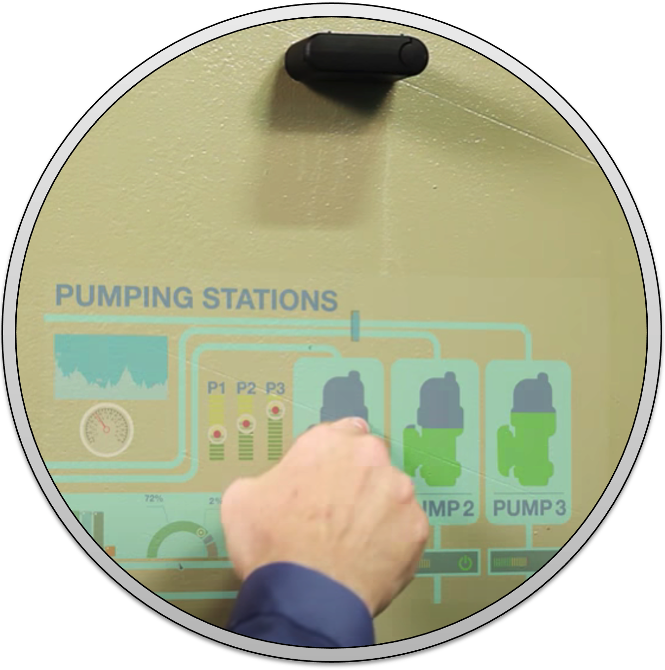
Given its projection nature and high contrast ratio, one can enable a display with virtually any form factor. Black pixels will not show on the display surface (effectively providing a transparent background in those areas). | |
Display on virtually any surface | 
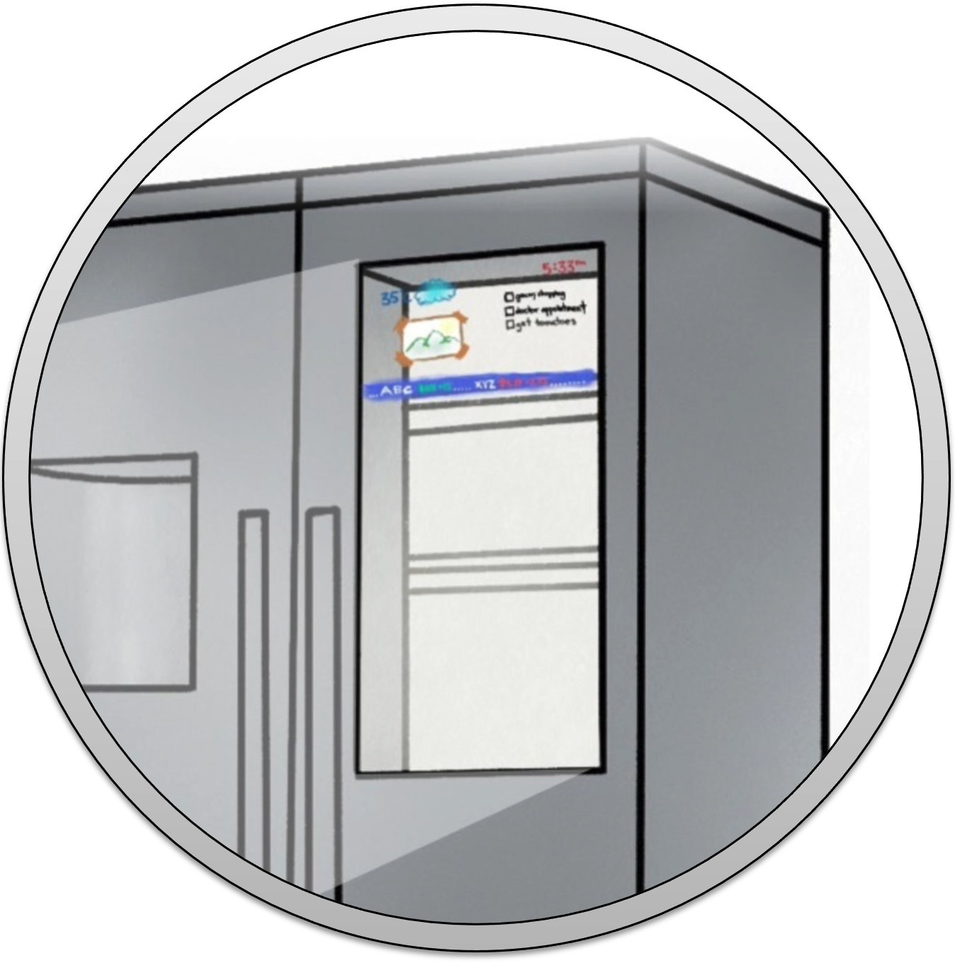
Projection will display on virtually any surface. Warping can be used to geometrically compensate for irregular-shaped display surfaces. | |
Small size, large image | 
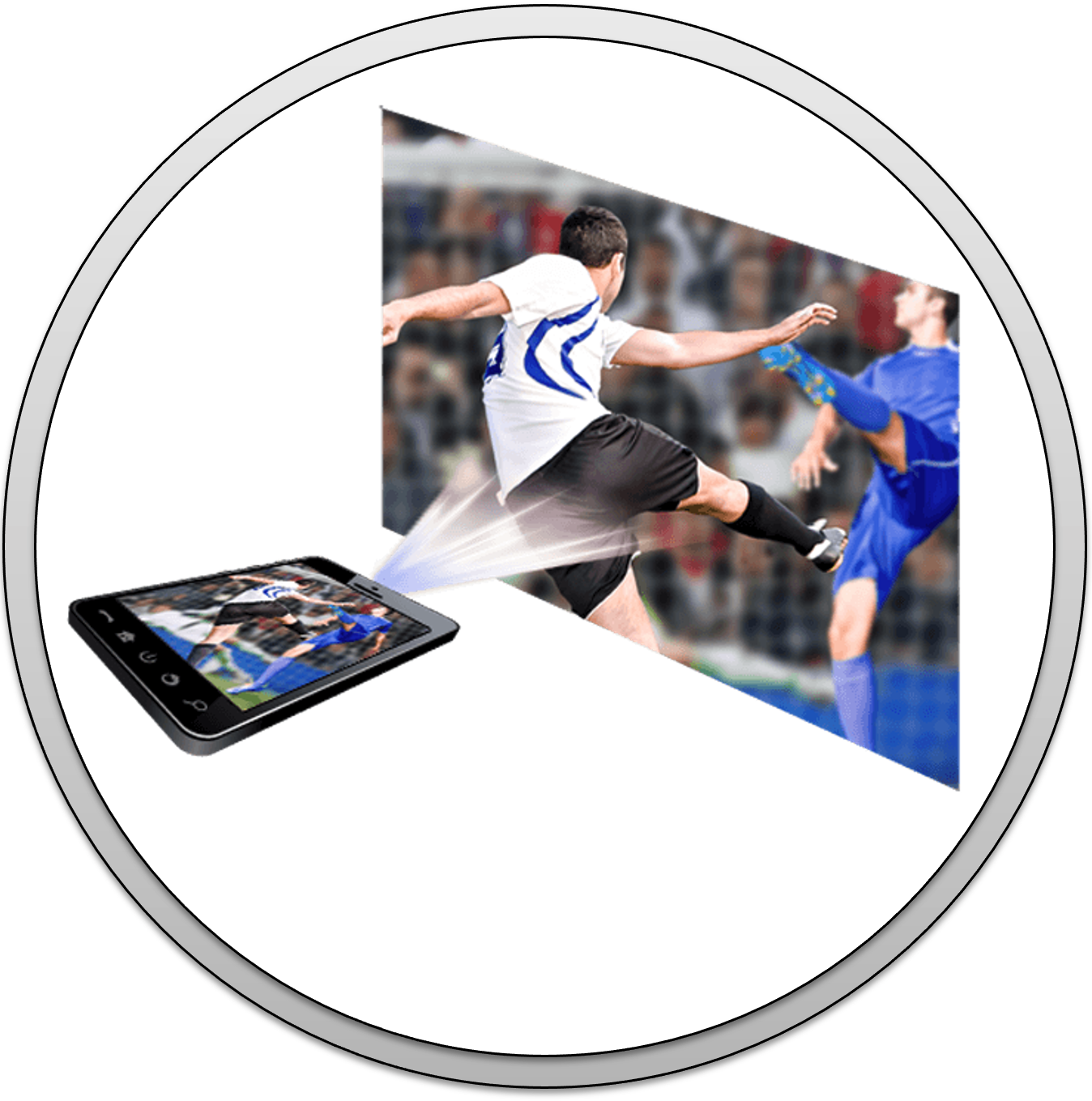
The DLP technology optical architecture and pixel design allows for extremely small-form factors compared to the image displayed. | |
Only visible when needed | 
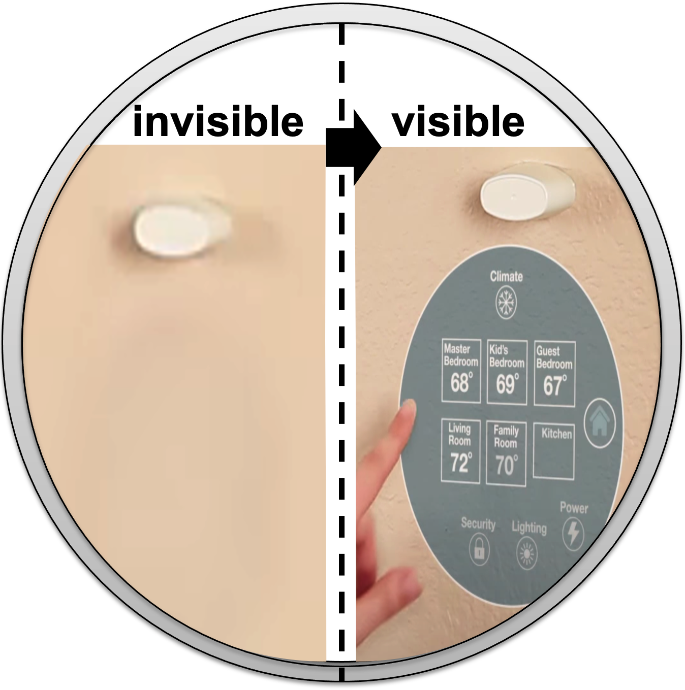
DLP projection display can be turned on and off on demand. The display disappears when it is turned off. |
Customers can learn how to promote features enabled by DLP technology by visiting the DLP Products Messaging and Icons Guidelines document (requires a myTI login).
DLP technology benefits outlined by application when visiting the web sites shown in Table 2-2.
Website | Application Examples |
---|---|
Applications for DLP Pico chipsets | Pico projector, Enterprise portable
projector, Laser TV <85", smart home displays, industrial displays (DLP signage,
humanoids, commercial gaming), virtual reality/augmented reality glasses,
smartphones and tablets (mobile accessories), and more. |
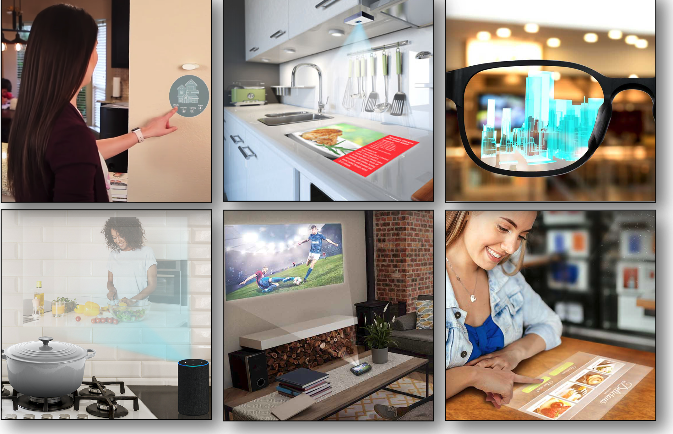
Applications for DLP Standard chipsets | Laser TV > 85", smart projector,
digital signage, enterprise projector, large venue, and cinema. |
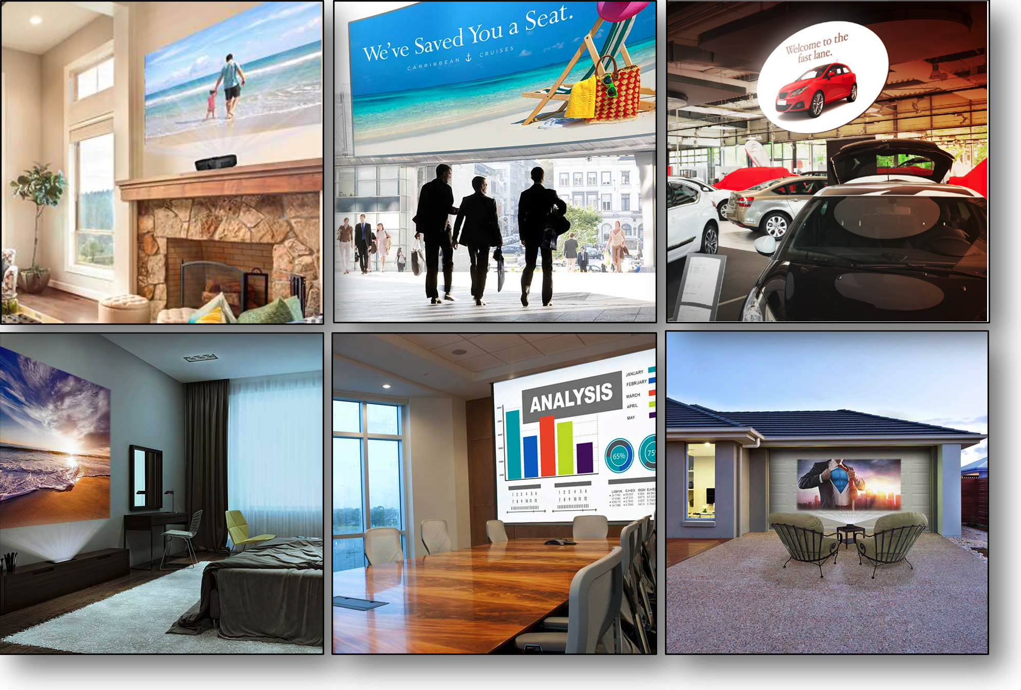
Some developers ask what does DLP stand for. The combination of these three letters do not have any meaning. DLP technology is the registered trademark brand name of the technology enabled by DMDs. Visit the Texas Instruments DLP® Brand and Logo Guidelines for additional information.
Texas Instruments DLP technology is a fast-switching micro-electro-mechanical systems (MEMS) technology that modulates light using a digital micromirror device (DMD) Figure 3-1. DMDs vary in resolution and size and can contain over 8 million micromirrors. Each micromirror can represent either one or more pixels on a display. The micromirrors are independently controlled and synchronized with color sequential illumination to create stunning images on virtually any surface. In some cases, the combination of the speed of the DLP chip, proprietary algorithms, and an optical actuator located inside the optical engine, can increase pixel density achieving an effective pixel pitch as small as 2.7μm (2.7μm : 5.4μm TRP pixel node using a 4-way actuator).
Here is a video that illustrates how DLP technology works to create a stunning image.
The display system starts with a video input signal and results in a stunning projected image. A display system needs three main components to operate: DMD, DLP display controller, and power management integrated circuit (PMIC). Figure 4-1 illustrates the typical block diagram of an LED DLP display system. You can also click here for a video that covers the block diagram of a DLP display system in detail.
The display system requires two primary connections: power and data. Power must be supplied to the DLP PMIC. Digital video data (including 24-bit RGB, DSI, or Vx1) must be supplied to the DLP display controller chip. A media processor, which accepts external sources like HDMI and processes streamed online content, sends digital video data out to the DLP display controller. Alternatively, a product's application processor, such as in a smartphone or tablet, can also send digital video data to the DLP display controller.
Table 4-1 provides some general guidelines on part number nomenclature for the DLP display chipset.
Component | Part Number Description |
---|---|
DMD | DMD part number begins
with the letters DLP followed by two numbers that
represent the active array diagonal in inches. Following digits vary
for each unique component. Example: DLP4710, DLP DMD with .47-inch diagonal |
Display controller | DLP display controllers
begin with the letters DLPC followed by other digits that vary for each unique component. Example: DLPC3439, DLP Pico .47 1080p display controller |
PMIC | DLP PMIC components
begin with the letters DLPA followed by other digits
that vary for each unique component. Example: DLPA2000, DLP Pico PMIC supporting up to 200mA of LED drive current |
The display system is split up in electronics and optical module hardware.
The electronics portion of the display system starts with a video input signal (for example, 12/16/18/24-bit RGB (red, green, blue) parallel, DSI, FPD-Link or Vx1 interfaces, typically driven by an application or media processor. The output of the electronics portion includes video signal to the DMD commonly using low voltage differential signaling (LVDS) or Sub-LVDS, illumination drive, and power. Figure 4-2 shows an example of the electronics hardware.
Table 4-2 includes the components of the electronics portion of the display system.
Component | Description |
---|---|
Applications processor | The function of the applications processor is to deliver the video signal to the DLP display system as well as inter-integrated circuit (I2C) interface to provide command and control functions. Any video-capable processor should be able to handle this task. |
Display controller | The DLP display
controller is the digital interface between the DMD and the rest of
the system. The controller takes digital input from an applications
processor and drives the DMD over a high speed interface. The DLP
controller also generates the necessary signals (data, protocols,
timings) required to display images on the DMD. Each display controller has a software user’s guide that details all its supported video handling functions, which will vary depending on the DLP chipset selected. To see an example software programmer’s guide for the .47 1080p DLP Pico chipset (DLP4710), see the DLPC3439 Software Programmer’s Guide. Video signal inputs
DMD signal outputs
The display controllers support image processing that helps optimize the image quality displayed, including data compression. A DLP Light Control chipset should be used if precise pixel to pixel mapping is required (typically used in structured lighting applications, learn more here). Image processing features depending on the chipset could include TI DLP® IntelliBright™ Algorithms for the DLPC343x Controller, DLP BrilliantColor™ technology, image keystone correction, warping, blending, frame rate conversion, integrated support for 3-D displays and more. Some systems require dual controllers to format the incoming data before sending it to the DMD. The DMD and its appropriate controller are required to be used together in a system design to ensure reliable operation. |
FPGA | Some chipsets
incorporate a technology which creates either two or four pixel
images on the screen from a single DMD micromirror. This is
accomplished through a combination of proprietary image processing
coupled with an optical actuator. The actuator is an opto-mechanical
element which is positioned in the optical path between the DMD and
the projection lens, and which has the ability to slightly alter the
direction of the projection light rays. A 2-way actuator can direct
light into two discrete directions, and a 4-way actuator can direct
light into four discrete directions. The proprietary image
processing converts the image data (from the customers application
processor) into either two or four sub-frames of data. These
sub-frames of data are then displayed on the DMD, synchronized with
the direction-state of the actuator. For chipsets which incorporate
this technology, the image processing is performed in an FPGA which
sits in the data path between the customers application processor
and the DLP controller. This FPGA is designed to receive data in the
same manner that a DLP controller would, and generate both the
sub-frame data as well as actuator control signals:
|
PMIC, LED drive, and motor driver | In most cases, a DLP
PMIC is responsible for providing input power to the DLP display
controller, DMD, and LED illumination components. The PMIC takes
care of supplying core voltages related to the DLP chipset and
gently power sequencing the DMD to ensure correct operation. It also provides other monitoring and protection functions, and dynamic LED control based on image color content (for example, TI DLP® IntelliBright™ Algorithms for the DLPC343x Controller). Integration of the power supply and LED driver circuitry in a small IC not only allows for small-size electronics to be designed, but also reduces the product design cycle time. A motor driver is also needed for systems that include a color wheel. This capability provides a color wheel motor drive control for phosphor laser illumination-based applications, as well as switching regulators and adjustable linear regulators for customer designed peripherals. It supports two peripherals by supplying three fan drivers and one 3-phase Back electromotive force (BEMF): motor driver or controller for a color wheel. |
Flash memory | Application-specific configurations are stored in the Flash memory. This component is typically placed on the electronics board or the DMD flex cable. |
DLP display controller and PMIC that accompany the DLP Pico DMDs are very small enabling extremely compact display products. Figure 4-3 shows both sides of an example printed circuit board design (estimate only) with the DLPA2000 PMIC and the DLPC3430 controller device, which drives a .2 WVGA (DLP2010) DMD.
The DMD, along with its associated electronics, an illumination source, optical elements, and necessary mechanical components, are combined into a compact and rugged assembly known as an optical module or light engine (Figure 4-4). The optical module is the core display component of the system. Optical modules can be of various sizes depending on the application and requirements. In general, the higher the brightness, the larger the size of the optical module due to the use of larger illumination sources, optics, DMDs, and thermal management components such as heat sinks and fans.
The optics portion of the display hardware system starts with electric signals going into an optical module housing that include all the components needed to create a projected image. General information about optical modules are located here for DLP Pico chipsets and here for DLP standard chipsets.
The DMD is connected to the DLP Pico controller by a flex cable or board-to-board connector. The LEDs in the optical module are connected with wires to the DLP PMIC (LED driver). System boards, fans, heat sinks, mechanical parts, switches, and other parts are assembled into a compact and robust final product around the optical module.
Figure 4-5 shows the optical components that can be included in an optical module. Click here to watch a video of an example optical module reference design (.23 qHD DMD; DLP230GP). Keep in mind that details of an optical module may not be relevant for a company that is planning to source a mass production optical engine. To read an application note that covers in detail how to specify an optical module, see TI DLP® Pico™ System Design: Optical Module Specifications. Also, click here to search for optical modules in mass production available for purchase. Figure 4-5 shows an optical module design example from DLP2010 DMD Optical engine reference design.
Components | Description |
---|---|
DMD | The digital micromirror
device is the component that houses the active digital micromirror
array, which allows the creation of a color plane, which enables the
projected image in combination with the illumination source. Each
DMD has the following unique characteristics:
|
DMD mounting mechanism |
The mounting of the DMD includes several needs: (a) proper placement of the DMD’s active array relative to the optical axis of the application, (b) a dust-proof seal between DMD and the optical assembly chassis, (c) reliable electrical connection, and (d) proper thermal management. to learn more about mounting concepts for various DLP chipsets, see Mounting Hardware and Quick Reference Guide for DLP® Advanced Light Control DMDs. |
DMD flex cable |
Cable used to transport electrical signals between the DMD and the display controller. |
Illumination source (color mechanism) |
DLP technology is
illumination source agnostic. The illumination sources that are
broadly available today are RGB LED and laser phosphor. RGB LED illumination. This illumination scheme uses red, green, and blue LEDs displayed with a single-color plane refresh rate. In some cases, a fourth LED will be used to increase brightness, although this brightness increase is penalized heavily against power efficiency. A 3-channel architecture could support brightness efficiency over 20 lumens/Watt (lm/W), while a 4-channel architecture will support brightness efficiency lower than 10 lm/W. Laser phosphor illumination. This illumination approach uses a single blue laser source diffused in combination with one or two phosphor color wheels to provide RGB light sources. Some implementations add a red or green channel to boost color performance. RGB Laser illumination. This illumination approach uses red, green, and blue laser sources. A de-speckler optical element is typically used for this implementation to improve image quality, although it is not required. |
Optical actuator (if needed) |
The DMD fast speed
allows a use of an optical actuator. 2-way and 4-way actuators that
meet TI specifications are used to increase on-screen resolution
while retaining the optical benefits of a 5.4μm pixel node. 2-way actuator, products like the DLP Pico .33 1080p (DLP3310) use a 2-way actuator to double the on-screen resolution of the DMD active array. 4-way actuator, products like the DLP Standard .47 4K (DLP471TE) use a 4-way actuator to quadruple the on-screen resolution of the DMD active array |
Homogenizer | The function of the homogenizer is to make the intensity profile of the light source to be more uniform. Typically, a fly’s eye array or light tunnel are used for this purpose. The optical element is located between the illumination source and the DMD. |
Projection lens | The purpose of the projection lens is to magnify the image coming from the DMD to the display surface. It also determines the throw ratio, defined as the distance between the projection lens and the display surface divided by the width of the displayed image. It also determines the image offset of the projection lens relative to the display surface. Watch this video to learn more about throw ratio and image offset. |
Illumination projection interface |
This optical element is responsible to interface between the DMD and projection optics. A few options include field lens, non-telecentric, total internal reflection (TIR) prism, and reverse TIR (RTIR) prism. |
Thermal management | To ensure the proper operation of the optical module, it is important to consider thermal management for the DMD and the illumination sources. Watch this video to see an innovative example of thermal management for a very small projection-based smart display. |
Watch this video to get more details on common projection lens specifications, including throw ratio definition, offset definition, and telecentric and non-telecentric architecture comparison.
There are several factors to consider selecting the correct chipset. To get started quickly, there are resources available that you can leverage as shown in Table 5-1.
Resource | Example |
---|---|
To receive a comparison of all the DLP display chipsets available today, see the Texas Instruments DLP® Display & Projection Chipset Selection Guide. | |
Watch this video to receive some general idea on how to select the correct chipset for your application. |
The following qualifiers can help you down select the DLP chipset that you need for your display application:
Portfolio overview: DLP display products have a wide range offering starting at a nHD resolution supporting 50 lm up to 4K resolution supporting over 10,000 lm. There are two general offerings: