SLOU583 September 2024 OPT101 , OPT3001 , OPT3001-Q1 , OPT3002 , OPT3004 , OPT3005 , OPT3006 , OPT3007 , OPT4001 , OPT4001-Q1 , OPT4003-Q1 , OPT4048 , OPT4060
2.2.3 Launching the LIGHTSOURCE01EVM Software
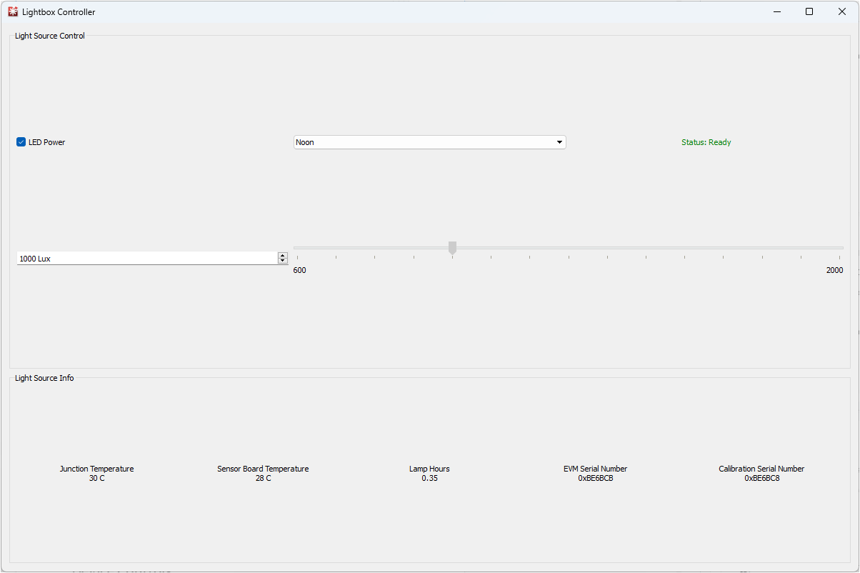
With the LIGHTSOURCE01EVM properly connected, launch the Latte LIGHTSOURCE01EVM GUI software from the Windows Start menu. The software launches with a screen shown in Figure 2-6.
 Figure 2-6 LIGHTSOURCE01EVM Main
Operating Screen
Figure 2-6 LIGHTSOURCE01EVM Main
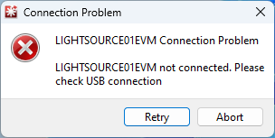
Operating ScreenIf the message shown in Figure 2-7 appears when the LIGHTSOURCE01 GUI software is launched, the EVM is not detected.
 Figure 2-7 Hardware Error Message
Check the USB connection and that the LIGHTSOURCE01EVM appears in the device manager. The EVM must occupy two COM ports: one for control and the other for data. The control port serves to send a receive the serial commands, while the data port is used for the actual transfer of data to and from the device. Refer to the following figure for an example of what the device manager must look like when connecting the device.
 Figure 2-8 COM Ports
If you are using Windows 7, or if the Windows device manager shows 2 USB Serial Devices under as other devices when the EVM is plugged in instead of COM ports, refer to Section 7.1.