SLUAAY2 December 2024 ISO5451 , ISO5451-Q1 , ISO5452 , ISO5452-Q1 , ISO5851 , ISO5851-Q1 , ISO5852S , ISO5852S-EP , ISO5852S-Q1 , UCC21710 , UCC21710-Q1 , UCC21717-Q1 , UCC21732 , UCC21732-Q1 , UCC21736-Q1 , UCC21737-Q1 , UCC21738-Q1 , UCC21739-Q1 , UCC21750 , UCC21750-Q1 , UCC21755-Q1 , UCC21756-Q1 , UCC21759-Q1
7.1 Short-Circuit Bench Measurement Setup
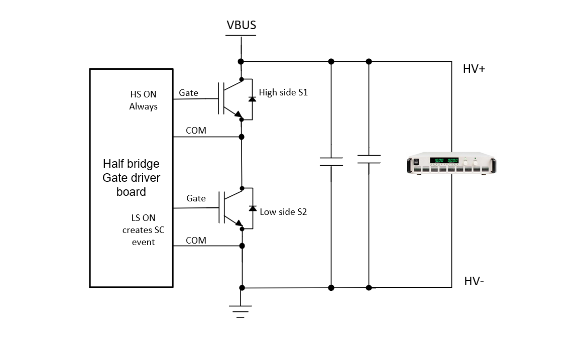
To exercise short-circuit event, a half-bridge gate driver board UCC21710QDWEVM-054 is used. This half-bridge board is capable of doing double pulse or SC testing. To exercise SC, the high side driver input is permanently set to high and the low side gate driver is turned on while the high sides switch is on.
High voltage power supply + bulk capacitance used as HV source. The schematic representation of the SC testing is shown in Figure 7-1.
 Figure 7-1 Half Bridge SC Schematic
Representation
Figure 7-1 Half Bridge SC Schematic
RepresentationIGBT (FF800R12KE7) and SiC (CAB450M12XM3) power modules are used to collect data for the SC event. VSC-based protection approach used to capture SC event for both DESAT and OC capable gate drivers.
The power modules key parameters are shown in Table 7-1.
| SiC CAB450M12XM3 | IGBT FF800R12KE7 | |
|---|---|---|
| VCE/VDS (V) IC/ID (A) | 1200V 450A |
1200V 800A |
| Qg | 1330 nC (Vds=800V) | 12.8 uC (Vcc=600V) (10x) |
| Cies /
Ciss, Cres/ Crss |
38 nF, 90 pF | 122 nF (3x), 0.6 nF (6x) |