SLUAAY2 December   2024 ISO5451 , ISO5451-Q1 , ISO5452 , ISO5452-Q1 , ISO5851 , ISO5851-Q1 , ISO5852S , ISO5852S-EP , ISO5852S-Q1 , UCC21710 , UCC21710-Q1 , UCC21717-Q1 , UCC21732 , UCC21732-Q1 , UCC21736-Q1 , UCC21737-Q1 , UCC21738-Q1 , UCC21739-Q1 , UCC21750 , UCC21750-Q1 , UCC21755-Q1 , UCC21756-Q1 , UCC21759-Q1


  1.   1
  2.   Abstract
  3.   Trademarks
  4. Introduction
  5. SiC and IGBT Characteristics
  6. Failure Modes
  7. Short-Circuit Protection Approaches
    1. 4.1 Short-Circuit Current-Based Protection Implementation
    2. 4.2 Short Circuit Voltage-Based Protection Implementation
  8. DESAT Circuitry Design
    1. 5.1 DESAT Circuit Component Selection
    2. 5.2 Effect of Parasitic Elements
    3. 5.3 Effect of Rlim on DESAT Noise
  9. Safe Shutdown
    1. 6.1 Safe Shutdown Mechanisms
    2. 6.2 Safe Shutdown Considerations
  10. Short-Circuit Test Setup and Data
    1. 7.1 Short-Circuit Bench Measurement Setup
    2. 7.2 SC Board Setup for Data Collection
    3. 7.3 Different Circuit Configurations for SC Testing
    4. 7.4 Bench Measurement Results
    5. 7.5 Overall Summary of SiC vs IGBT Power Module SC Observation
  11. Key Consideration in Designing SC Protection Circuit
  12. Summary
  13. 10References

Safe Shutdown Considerations

When safe shutdown is implemented, the power loop parasitic inductance plays a large role in the VCE/VDS overshoot profile and the shutdown time. Larger power loop parasitic inductance would increase the VCE/VDS overshoot with the same power switch di/dt, which is also why STO/2LTO are more desirable under this condition. Also, shutdown time can be reduced if parasitic inductance in the power loop is reduced. This includes power module stray inductance.
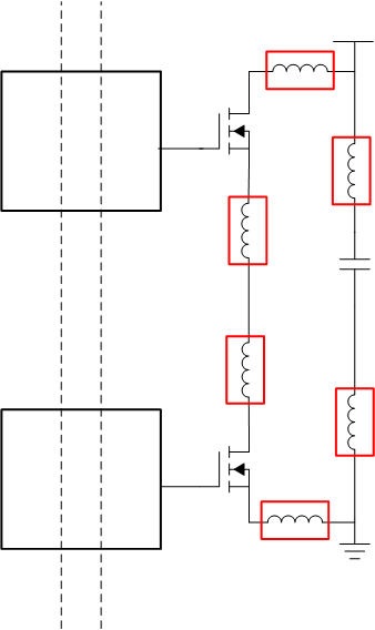
UCC21750Q1 Power Loop Inductance Figure 6-3 Power Loop Inductance