SLVAE57B February 2021 – October 2021 LM5050-1 , LM5050-2 , LM5051 , LM66100 , LM74202-Q1 , LM74500-Q1 , LM74610-Q1 , LM74700-Q1 , LM74720-Q1 , LM74721-Q1 , LM74722-Q1 , LM7480-Q1 , LM7481-Q1 , LM76202-Q1 , SM74611 , TPS2410 , TPS2411 , TPS2412 , TPS2413 , TPS2419
- Trademarks
- 1 Introduction
- 2 Reverse Battery Protection
- 3 ORing Power Supplies
- 4 Reverse Battery Protection using MOSFETs
- 5 Reverse Polarity Protection vs Reverse Current Blocking
- 6 What is an Ideal Diode Controller?
- 7 Automotive Transient protection with Ideal Diode Controllers
- 8 ORing Power Supplies with Ideal Diode Controllers
- 9 Integrated Ideal Diode Solution
- 10Summary
- 11References
- 12Revision History
6.2 Low Forward Conduction Loss
Forward voltage drop of schottky diodes increases the forward conduction power loss and requires thermal management using heat sink and requires PCB space leading to increased cost. Ideal diode controllers use an external MOSFET to reduce the forward voltage to 20 mV or lower, depending on the control scheme. Linear regulation control scheme maintains 20 mV forward voltage during most of the operating current range. Hysteretic ON/OFF control fully enhances the MOSFET to reduce the forward voltage and the forward drop is decided solely based on the MOSFET used.
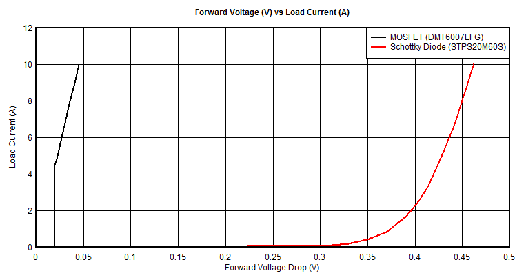
Forward voltage of the MOSFET DMT6007LFG driven by ideal diode controller is compared against forward voltage of schottky diode STPS20M60S in Figure 6-3. An ideal diode controller using linear regulation scheme regulates the forward voltage to low 20 mV up to load current = 20 mV / RDS(MIN) and load current higher than 20 mV / RDS(MIN) forward voltage solely depends on MOSFETs RRD(ON). In Figure 6-3, MOSFET is regulated to 20 mV forward voltage up to 5.7 A and beyond 5.7, a MOSFET is fully enhanced and forward voltage increases based on load current. At 10 A, low forward voltage drop is reduced to 35 mV against 465 mV using a Schottky diode. LM74722-Q1 ideal diode controller offers an even lower forward voltage drop of 13 mV, providing further improvement in power efficiency.
 Figure 6-3 Forward Voltage Vs Load Current
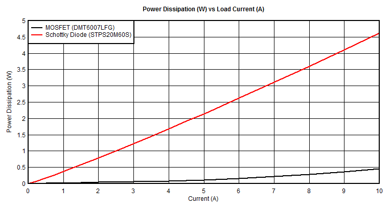
 Figure 6-4 Power Dissipation Vs Load Current
Figure 6-4 shows the power dissipation comparison between schottky diode and ideal diode controller. At a 10 A load current, DMT6005LPS-13 MOSFET dissipates 0.35 W of power, whereas schottky diode STPS20M60S dissipates 4.65 W of power leading to more than 10x power saving when using ideal diode controller and MOSFET.