SLOA170B July 2012 – January 2021 DRV8242-Q1 , DRV8412 , DRV8424 , DRV8424E , DRV8425 , DRV8425E , DRV8426 , DRV8426E , DRV8428 , DRV8428E , DRV8434 , DRV8434E , DRV8436 , DRV8436E , DRV8701 , DRV8702-Q1 , DRV8702D-Q1 , DRV8703-Q1 , DRV8703D-Q1 , DRV8705-Q1 , DRV8706-Q1 , DRV8800 , DRV8801 , DRV8802 , DRV8802-Q1 , DRV8811 , DRV8812 , DRV8813 , DRV8814 , DRV8818 , DRV8821 , DRV8823 , DRV8823-Q1 , DRV8824 , DRV8824-Q1 , DRV8825 , DRV8828 , DRV8829 , DRV8832 , DRV8832-Q1 , DRV8833 , DRV8834 , DRV8840 , DRV8841 , DRV8842 , DRV8843 , DRV8844 , DRV8846 , DRV8848 , DRV8870 , DRV8874 , DRV8874-Q1 , DRV8876 , DRV8876-Q1 , DRV8880 , DRV8881 , DRV8885 , DRV8886 , DRV8889-Q1 , DRV8899-Q1 , DRV8935 , DRV8955
4 PWM to RC Filter Method
The DAC function solution may result prohibitive for some circumstances. For example, not every microcontroller will contain a DAC block. Also, the added cost of a stand alone DAC function may not be favorable for the end application. Timers, on the other hand, are much more common place on today’s microcontroller offering.
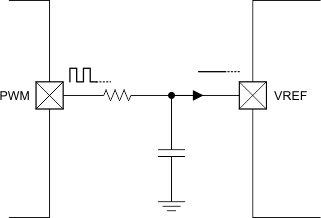
A simple technique to fashion a DAC channel by utilizing a timer function is to have the timer operate as a PWM generator into an RC filter, as shown on Figure 4-1. By modulating the PWM’s duty cycle, a directly proportional analog voltage can be obtained. The RC filter element must be configured so the output voltage has the least amount of ripple, as such variations may transfer into the regulated current output.
 Figure 4-1 PWM Timer and RC Filter Generates an Analog Voltage
Typical implementations around an RC filter based DAC may be a brushed DC motor requiring torque control or a stepper motor requiring a current during run time and a different current for position holding torque. In order for this topology to work as a DAC function capable of generating high resolution micro-stepping, the PWM frequency would need to be higher than the stepping rate.