SCDA017A September 2019 – July 2024 BQ24392 , HD3SS212 , HD3SS213 , HD3SS214 , HD3SS215 , HD3SS3202 , HD3SS3212 , HD3SS3220 , HD3SS3411 , HD3SS460 , TMUXHS4212 , TS3DV642 , TS3USB221 , TS3USB221A , TS3USB221E , TS3USB30 , TS3USB3000 , TS3USB3031 , TS3USB30E , TS3USB31 , TS3USB31E , TS3USB3200 , TS5USBA224 , TS5USBC400 , TS5USBC402 , TS5USBC41 , TUSB1042I , TUSB542
2.3 Signal Harmornics and Distortion
System designers want to use muxes to accomplish simple signal routing, and wish the impact of the physical mux to the signal itself is as small as possible. The time dependant differences between shapes of the input and output signals are generally referred to as distortion. If some fraction of the frequency components of the input signal exceed the system bandwidth, the system response to this portion of the signal lags. As a result, the output signal does not accurately reproduce the fastest transitions of the input signal. This results in output signals that may have lower amplitudes, and wider and rounder edges, than the corresponding features in the input signal.
This section looks at a square wave to see what causes the square shape. A complex waveform can be constructed from the sine (and cosine) waves of various amplitude and phase relationships. This is the basis of Fourier analysis.
For example, a square wave can be constructed from multiple sine waves at different frequencies. The sine waves added, in addition to the fundamental frequency, are called harmonics; a square wave has harmonics at odd multiples of the fundamental frequency. As higher harmonics are added, the result gets closer to an ideal square wave.
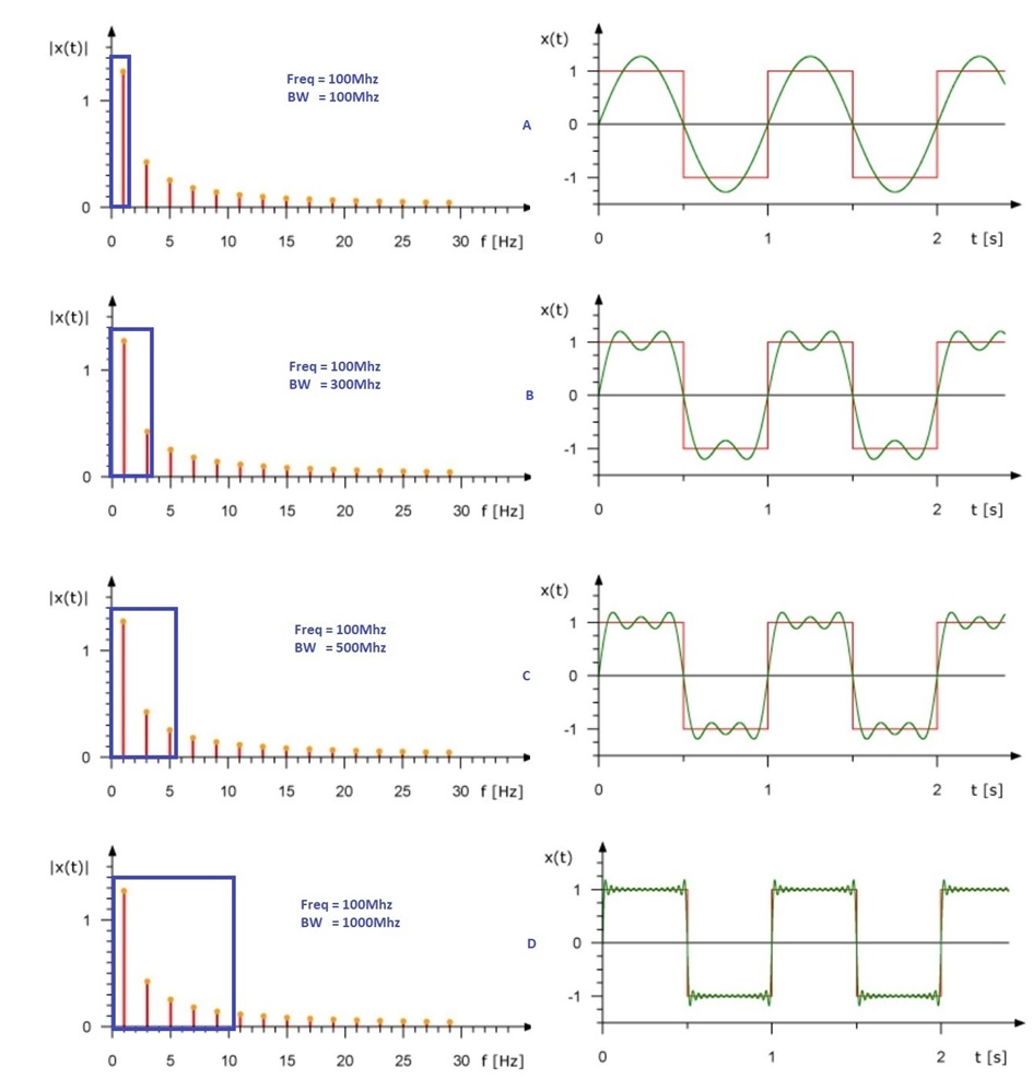
The amplitude of the harmonics is equal to 1/N, where N is the harmonic (1, 3, 5, 7…). Each harmonic has the same phase relationship to the fundamental. If constructing a square wave from just the first two harmonic components, the beginnings of how the square shape occurs can be seen (waveform B of Figure 2-2). Figure 2-2 shows that the red trace is the ideal square waveform, and the green trace is the waveform with Nth harmonic at the correct amplitude. Interfering frequencies must be much higher in frequency than the fundamental frequency. If the system requires that third, fifth, or even higher harmonics must be passed, the 3-dB cutoff frequency must be above these harmonics: three, five, or seven or more times the fundamental frequency. If using the fifth harmonic components zero, three, and five to construct the square wave, it really starts to take shape (Figure 2-2 waveform C). If using more than 10th harmonic components to construct the square wave, it is really close to the ideal square waveform (Figure 2-2 waveform D).
From these graphs, it is easily understood that the high frequency harmonic content, and not a DC component, is responsible for the shape of a square wave.
 Figure 2-2 Square Wave With Different
Harmonics