SLVA505A February 2012 – July 2024 DRV8800 , DRV8801 , DRV8802 , DRV8803 , DRV8804 , DRV8805 , DRV8806 , DRV8811 , DRV8812 , DRV8813 , DRV8814 , DRV8818 , DRV8821 , DRV8823 , DRV8824 , DRV8828 , DRV8829 , DRV8830 , DRV8832 , DRV8832-Q1 , DRV8833 , DRV8834 , DRV8835 , DRV8836 , DRV8837 , DRV8840 , DRV8841 , DRV8842 , DRV8843 , DRV8844 , DRV8870 , DRV8871 , DRV8872
- 1
- Abstract
- Trademarks
- 1Factors Limiting the Maximum Output Current of a Motor Driver
- 2TI Motor Driver OCP Operation
- 3TI Motor Driver Data Sheet Ratings
- 4References
- 5Revision History
1.5 Thermal Estimations
Being able to accurately predict junction temperature under certain operating conditions can make sure the motor driver operates within safe thermal specifications and prevent overheating and potential damage. Doing so not only enhances the reliability and lifespan of the motor driver but also maintains a designed for performance by preventing thermal stress related issues. There are several key parameters to consider when calculating the junction temperature of motor drivers such as, ambient temperature, power dissipation, thermal resistance, transient time for loading, PWM or no PWM, and so on. These calculations can further optimize thermal aspects of the design such as heatsink sizing, airflow management, and makes sure the device can be operating below the integrated thermal shutdown protection features.
The DRV824x-Q1 family of devices offers a junction temperature estimation calculator to makes sure the motor driver operates with safe thermal limits. Using the DRV824x-Q1 data sheets, transient thermal resistance tables can be used as a reference for specific transient cases to be used with the thermal calculator.
 Figure 1-5 Transient Thermal Impedance
(RθJA) and Current Capability - Full-Bridge
Figure 1-5 Transient Thermal Impedance
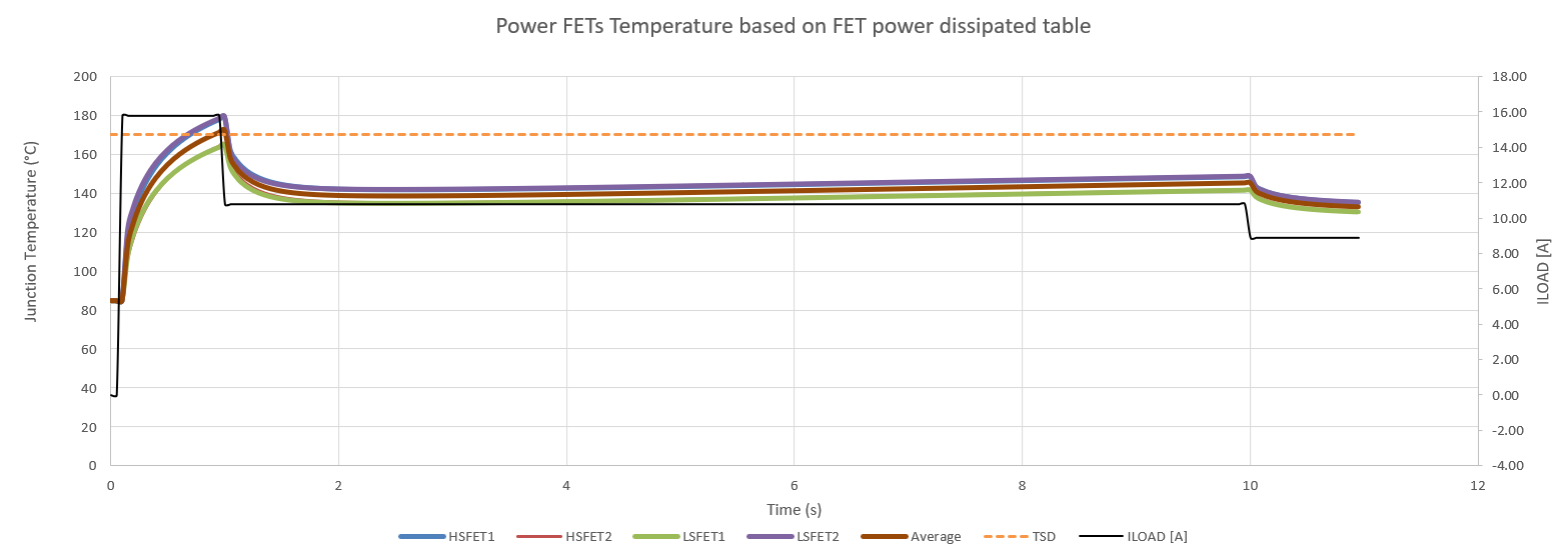
(RθJA) and Current Capability - Full-BridgeWhen using this calculator, the user inputs desired transient current values over a specified time and the calculator outputs a graph of the how the junction temperature changes based on the MOSFETs power dissipation. The MOSFETs power dissipation is composed of two sources, from conduction losses while the MOSFET is on and switching losses during PWM based current regulation. For more details on the total power dissipation formulas, see Calculating Power Dissipation for a H-Bridge or Half Bridge Driver.
 Figure 1-6 Junction Temperature
Estimation
Figure 1-6 Junction Temperature
EstimationThe thermal simulation previously is based on using 40mm x 40mm x 16mm, 4-layer PCB using 2 oz Cu on the top and bottom layers, 1 oz Cu on internal planes. With a starting ambient temperature of 85°C and transient current capabilities estimated with only conduction losses (no PWM) used from the data sheet.
Thermal estimations are important to maintain reliability and performance under varying thermal conditions. If the junction temperature exceeds the overtemperature shutdown threshold, the device is outside of safe operating conditions and motor driver operating current must be reduced to lower power dissipation and effectively manage heat. These estimations determine the maximum current the motor driver can handle without overheating.