SLVA505A February 2012 – July 2024 DRV8800 , DRV8801 , DRV8802 , DRV8803 , DRV8804 , DRV8805 , DRV8806 , DRV8811 , DRV8812 , DRV8813 , DRV8814 , DRV8818 , DRV8821 , DRV8823 , DRV8824 , DRV8828 , DRV8829 , DRV8830 , DRV8832 , DRV8832-Q1 , DRV8833 , DRV8834 , DRV8835 , DRV8836 , DRV8837 , DRV8840 , DRV8841 , DRV8842 , DRV8843 , DRV8844 , DRV8870 , DRV8871 , DRV8872
- 1
- Abstract
- Trademarks
- 1Factors Limiting the Maximum Output Current of a Motor Driver
- 2TI Motor Driver OCP Operation
- 3TI Motor Driver Data Sheet Ratings
- 4References
- 5Revision History
2 TI Motor Driver OCP Operation
TI motor drivers all implement a robust OCP scheme preventing damage to the IC in the event of excessive output current. TI devices are protected against dead shorts, or soft shorts, between the outputs, as well as between each output and the supply voltage or ground.
TI's OCP implementation typically includes two components:
- A fast-acting analog current limit, typically tens of nanoseconds, to limit the current in the output to a level that is safe for the IC and the package. It does this by operating the output FET in a linear region, dissipating significant power.
- A digital time is started as soon as the current rises above a predefined threshold, the OCP current. When this timer reaches OCP deglitch time, typically a few microseconds, if the current level is still above the threshold, the output is disabled.
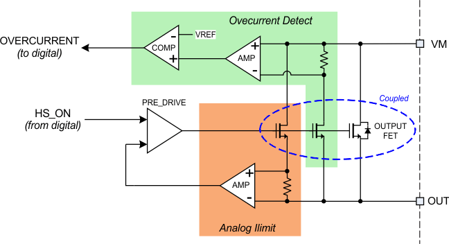
TI implements separate OCP circuits for each output FET, so each FET is protected from shorts to either the supply, the ground, or to other outputs. The OCP circuit is independent of any current regulation (current chopping or ITRIP) circuitry and does not depend on any external components.
Figure 2-1 shows a simplified schematic of the analog portion of a typical TI motor driver OCP circuit. A high-side FET is shown; there is a similar circuit for the low-side FET.
 Figure 2-1 Simplified OCP Schematic
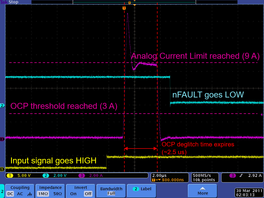
Figure 2-2 shows an oscilloscope capture of a short circuit event using a TI DRV8813 motor driver. In this case, the output was enabled with a direct short across the outputs. The yellow trace is the input signal, the blue trace is the fault-output signal, and the pink trace is the current through the output stage.
Initially, the current rises quickly. After a brief overshoot, which is not a problem for the output stage, the current is limited to approximately 9 A by the analog current limit. In approximately 2.5 µs, as the OCP deglitch time expires, the current is still at the analog current level of 9 A, exceeding the OCP level. In this case, the OCP level is approximately 3 A. At this point, the output is disabled and the current drops to zero. Shortly thereafter, the fault signal is driven low indicating that the OCP event has occurred to the rest of the system.
 Figure 2-2 Oscilloscope Capture of a
Short Circuit Event Using TI DRV8813 Motor Driver
Figure 2-2 Oscilloscope Capture of a
Short Circuit Event Using TI DRV8813 Motor DriverDepending on the individual device, after an OCP event occurs, the device may latch in an off state until some intervention is made by the system (like the application of a reset signal), or the output may automatically re-enable after a delay time.
If the device uses an automatic retry and is operating into a continuous short circuit, the power dissipated by the analog current-limit circuit causes the device to heat up. At some point, the die may reach the overtemperature shutdown temperature. In any case, the device is protected from damage.