SLUAAF4A may 2021 – april 2023 TPS51397A , TPS53318 , TPS53319 , TPS53353 , TPS53355 , TPS548A28 , TPS548A29 , TPS548B22 , TPS548B28 , TPS548D22 , TPS549B22 , TPS549D22 , TPS54J060 , TPS54J061 , TPS54JA20 , TPS54JB20 , TPS566235 , TPS568215 , TPS568230 , TPS56C215 , TPS56C230
3 Bode Plot Measurements
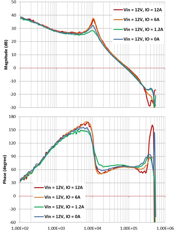
Figure 3-1 shows the Bode plot measurement results using the test setup shown in Figure 1-3 using the TPS53319 using an external DCR injection circuit and programmed to 1.2-V output. A capacitor value of 0.22 µF is chosen for Cpass and 22 nF for Cp. By adjusting Rp and Cff, the crossover frequency is set at one-sixth of the switching frequency with a phase margin of 66 degrees.
 Figure 3-1 Bode Plots Measured With the
Proposed Test Setup