-
Understanding the I2C Bus SLVA704 June 2015 INA209 , INA219 , INA220 , INA220-Q1 , INA223 , INA226 , INA226-Q1 , INA228 , INA228-Q1 , INA230 , INA231 , INA233 , INA234 , INA237 , INA237-Q1 , INA238 , INA238-Q1 , INA3221 , INA3221-Q1 , LM8323 , LM8325-1 , LM8327 , LM8328 , LM8330 , LM8333 , LM8335 , OPT3001 , OPT3004 , P82B715 , P82B96 , PCA6107 , PCA9306 , PCA9306-Q1 , PCA9515A , PCA9515B , PCA9518 , PCA9534 , PCA9534A , PCA9535 , PCA9536 , PCA9538 , PCA9539 , PCA9543A , PCA9544A , PCA9545A , PCA9546A , PCA9548A , PCA9554 , PCA9554A , PCA9555 , PCA9557 , PCF8574 , PCF8574A , PCF8575 , PCF8575C , TCA4311A , TCA5405 , TCA6408A , TCA6416A , TCA6418E , TCA6424A , TCA6507 , TCA8418 , TCA8418E , TCA8424 , TCA9406 , TCA9509 , TCA9517 , TCA9517A , TCA9534 , TCA9534A , TCA9535 , TCA9538 , TCA9539 , TCA9539-Q1 , TCA9543A , TCA9544A , TCA9545A , TCA9546A , TCA9548A , TCA9554 , TCA9554A , TCA9555 , TCA9617A , TCA9617B , TCA9800 , TCA9801 , TCA9802 , TCA9803
-
Understanding the I2C Bus
Understanding the I2C Bus
Understanding the I2C Bus
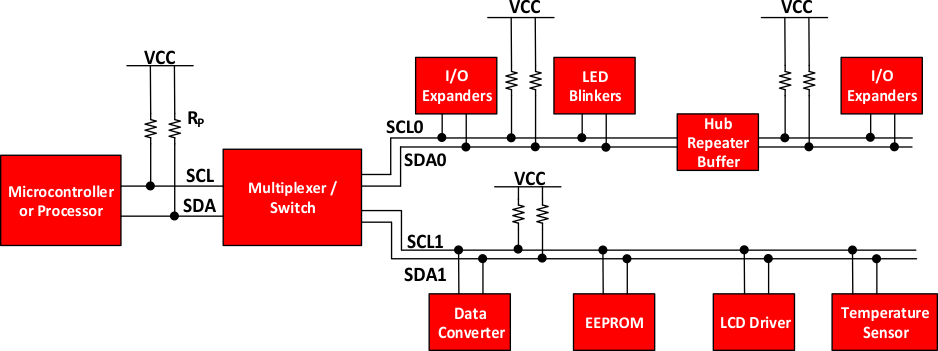
The I2C bus is a very popular and powerful bus used for communication between a master (or multiple masters) and a single or multiple slave devices. Figure 1 illustrates how many different peripherals may share a bus which is connected to a processor through only 2 wires, which is one of the largest benefits that the I2C bus can give when compared to other interfaces.
This application note is aimed at helping users understand how the I2C bus works.
Figure 1 shows a typical I2C bus for an embedded system, where multiple slave devices are used. The microcontroller represents the I2C master, and controls the IO expanders, various sensors, EEPROM, ADCs/DACs, and much more. All of which are controlled with only 2 pins from the master.
 Figure 1. Example I2C Bus
 Trademarks
All trademarks are the property of their respective owners.