SLVAE36A September 2018 – July 2021 LM43600 , LM43601 , LM46001 , LM46002 , LM5160A , LM5161 , LM5165 , LM5166 , LM61460-Q1 , LM73605 , LM73605-Q1 , LM73606-Q1 , LM76003 , LMR33620 , LMR33630 , LMR36006 , LMR36015 , LMR36500 , LMR36501 , LMR36502 , LMR36503 , LMR36506 , LMZ36002 , LMZM23600 , LMZM23601 , LMZM33602 , LMZM33603 , LMZM33606 , TPS54218 , TPS54360B , TPS54418 , TPS54424 , TPS54560B , TPS54618 , TPS55010 , TPS62148 , TPS62821 , TPS62822 , TPS62823 , TPS82130 , TPS82140 , TPS82150 , TPSM365R15 , TPSM365R3 , TPSM365R6
3 Thermal limitations and power budgets
Because PLCs operate in harsh factory environments, they are enclosed in a cabinet where airflow is either constricted or unavailable. In many cases, the use of a cooling fan is prohibited due to the presence of dust, corrosive elements, or other material limitations. Integrated circuits dissipate heat when operating, especially power management devices, so it is important to choose a high efficient power solution to minimize heat. System long-term reliability is degraded under excessive thermal stressing. Heat also affects the accuracy of any analog sensing circuitry. There is a good chance that the amount of power is limited from the 24-V source supplied to the PLC. Reducing the power dissipation of the point-of-load power solution will increase the power budget of a module and allow the PLC to be differentiated in the marketplace. Additional available power allows faster microprocessor clocking speeds, higher accuracy accurate data converters, or additional memory to improve the performance of the PLC against the competition. Harsh factory environments may experience extreme ambient temperature. It is more useful to specify and rate DC/DC converters by their minimum and maximum junction temperature rather than their ambient temperature. Many DC/DC converters are rated at 150C maximum junction temperature to provide more thermal headroom. An operating temperature range parameter is available within the parametric search engine of step down converters which makes it easy to select products with high operating temperature capability.
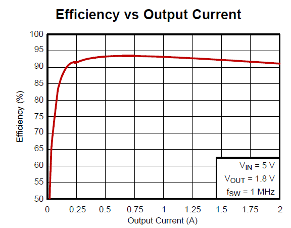
Operating a DC/DC converter at peak efficiency is an excellent way to minimize the conduction and switching losses of the DC/DC converter’s power MOSFETs. The efficiency of the 2-A TPS54218 design de-rated to 0.5 A is shown in Table 3-1 compared to the 0.5-A TPS62231 using Webench®. Obviously, the smaller MOSFETs of the TPS62231 allow a smaller package size, and the higher frequency allows smaller passive components for smaller solution size. However, the TPS54218 saves 140mW of energy, maximizing efficiency and improving thermal performance in applications that have limited airflow or constrained power budgets. The efficiency of TPS54218 can be further optimized as shown in Figure 3-1. Peak efficiency is about 93% around 0.5A at the knee of the curve which represents the optimal point between switching and conduction losses.
| Device | η | Pd (W) | Rds(on) | Frequency | Solution Size |
| TPS54218 | 87% | 0.13 | 20 mΩ/20 mΩ | 1.125 MHz | 122 mm2 |
| TPS62231 | 80% | 0.27 | 600 mΩ/350 mΩ | 3 MHz | 23 mm2 |
 Figure 3-1 Efficiency Curve of TPS54218