SLAA412B June 2009 – August 2020 LFC789D25 , LM237 , LM317 , LM317L , LM317M , LM317MQ , LM337 , LP2950 , LP2951 , LP2981 , LP2981A , LP2985 , MC79L , REG101 , REG102 , REG103 , REG104 , REG1117 , REG1117A , REG1118 , REG113 , SN105125 , TL1963A , TL317 , TL5209 , TL720M05-Q1 , TL750L , TL750M , TL750M-Q1 , TL751L , TL760M33-Q1 , TL780 , TL783 , TLE4275-Q1 , TLV1117 , TLV1117LV , TLV2217 , TLV700-Q1 , TLV70012-Q1 , TPPM0110 , TPPM0111 , TPPM0301 , TPPM0302 , TPPM0303 , TPS51100 , TPS51103 , TPS51200 , TPS61100 , TPS61107 , TPS61120 , TPS61121 , TPS61122 , TPS65020 , TPS65021 , TPS65022 , TPS650231 , TPS65023B , TPS65050 , TPS657052 , TPS65708 , TPS657095 , TPS701 , TPS70175-Q1 , TPS702 , TPS703 , TPS70345-EP , TPS704 , TPS707 , TPS70751-EP , TPS708 , TPS71 , TPS71025 , TPS712 , TPS71202-EP , TPS713 , TPS715-Q1 , TPS71501-EP , TPS715A , TPS715A-NM , TPS718 , TPS719 , TPS71H01 , TPS72 , TPS720 , TPS721 , TPS72118-EP , TPS722 , TPS723 , TPS725 , TPS726 , TPS727 , TPS728 , TPS73 , TPS730 , TPS731 , TPS73101-EP , TPS731125-EP , TPS73115-EP , TPS73118-EP , TPS73125-EP , TPS73130-EP , TPS73132-EP , TPS73133-EP , TPS73150-EP , TPS732 , TPS732-Q1 , TPS73201-EP , TPS73215-EP , TPS73216-EP , TPS73218-EP , TPS73225-EP , TPS73230-EP , TPS73233-EP , TPS73250-EP , TPS734 , TPS735 , TPS736 , TPS73601-EP , TPS73615-EP , TPS73618-EP , TPS73625-EP , TPS73630-EP , TPS73632-EP , TPS73633-EP , TPS737 , TPS737-Q1 , TPS73HD3 , TPS74 , TPS74201 , TPS74301 , TPS74401 , TPS74701 , TPS74801 , TPS74901 , TPS751 , TPS75103 , TPS75105 , TPS75125-EP , TPS752 , TPS752-Q1 , TPS75201-EP , TPS75201M-EP , TPS75215-EP , TPS75218-EP , TPS75225-EP , TPS75233-EP , TPS753 , TPS75301-EP , TPS75318-EP , TPS75325-EP , TPS75333-EP , TPS754 , TPS755 , TPS756 , TPS757 , TPS758 , TPS759 , TPS760 , TPS76201 , TPS763-Q1 , TPS766 , TPS767 , TPS767-Q1 , TPS76701-EP , TPS76715-EP , TPS76718-EP , TPS76725-EP , TPS76733-EP , TPS767D3 , TPS767D3-Q1 , TPS767D301-EP , TPS768 , TPS768-Q1 , TPS76801-EP , TPS76815-EP , TPS76818-EP , TPS76825-EP , TPS76833-EP , TPS76850-EP , TPS769 , TPS769-Q1 , TPS76901-HT , TPS770 , TPS77101-Q1 , TPS773 , TPS774 , TPS77401-EP , TPS775 , TPS775-Q1 , TPS77501-EP , TPS77515-EP , TPS77518-EP , TPS77525-EP , TPS77533-EP , TPS776 , TPS776-Q1 , TPS77601-EP , TPS77615-EP , TPS77618-EP , TPS77625-EP , TPS77633-EP , TPS777 , TPS778 , TPS779 , TPS780 , TPS781 , TPS782 , TPS786 , TPS789 , TPS790 , TPS791-Q1 , TPS79101-EP , TPS79133-EP , TPS79147-EP , TPS793-Q1 , TPS79301-EP , TPS79318-EP , TPS79333-EP , TPS793475-EP , TPS794 , TPS797 , TPS797-Q1 , TPS79718-EP , TPS79730-EP , TPS799 , TPS799-Q1 , TPS7A45 , TPS7A47 , UA723 , UA78 , UA78L , UA78M , UA78M-Q1 , UA79 , UA79M , UC1832 , UC1832-SP , UC1834 , UC1834-SP , UC1836 , UC282 , UC2832 , UC2832-EP , UC2833 , UC2834 , UC2834M , UC2835 , UC2836 , UC285 , UC382 , UC3832 , UC3833 , UC3834 , UC3836 , UC385 , UCC281 , UCC283 , UCC2837 , UCC284 , UCC381 , UCC383 , UCC384
4 Which Specification is for Your Application?
The user should know which noise specification of the LDO is to be used in the application, because there are some application where the Spectral noise density is pertinent and some applications where total (integrated) noise can be used. The following examples explain this.
- Consider an RF system, where an LDO powers a Voltage Controlled Oscillator (VCO). VCO takes two input signals and mixes them together. If the two signals are sin(ω1t) and sin(ω2)t, then the result is two outputs sin((ω1–ω2)t), sin((ω1+ω2)t) and harmonics. The RF signal chain following the VCO is typically a band-pass system tuned for only one frequency, that means, only higher frequency remains after mixing. Most broadband applications have very tight regulation on the frequency spectrum and the power in each band. For any band, the spurious noise has to be controlled to meet what is called the “transmit mask”. This mask is very important for agency certification of the final product. Any humps in the noise floor at higher frequencies may cause the transmitted signal to be outside of the transmit mask and thus fail the certification testing.
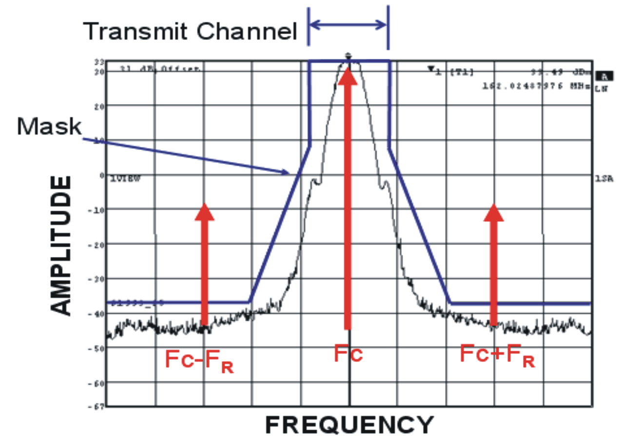
Now if the noise is present on the conductors that are supplying power or in the LDO output then that noise at a frequency, FR, gets mixed with the carrier frequency and produces two sidebands as shown in the Figure 4-1. If the noise is so high that the sideband produced due to noise is out of transmit mask then it results in failure of the system.
 Figure 4-1 Transmit Mask and Sidebands Due to Noise
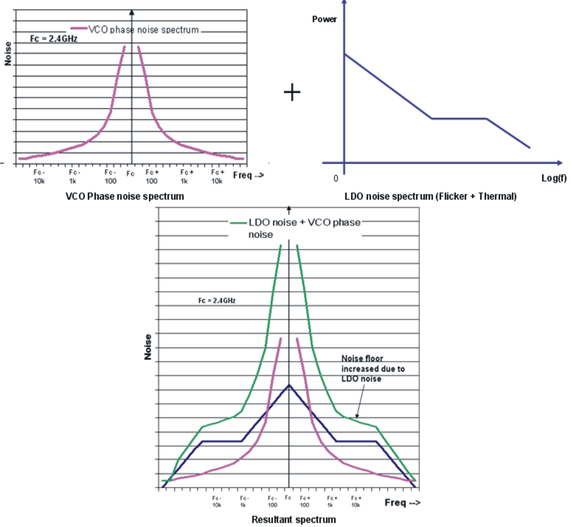
Also, if we assume that the RF system is working at a frequency of 2.4GHz, then LDO noise contributes to the VCO noise spectrum both above and below 2.4GHz with up to bandwidth of LDO. The LDO noise shown in Figure 2-1 adds to the original VCO noise plot which increases the VCO noise floor level around the center frequency.
 Figure 4-2 Increase in VCO Noise Floor Due to LDO Noise
So in this RF application the user should use Spectral Noise Density curve since the single noise number loses the frequency dependence and would not be an accurate representation of the final output.
- Consider a system in which LDO is powering an ADC or DAC. Any sampled system causes the high frequency noise to fold to lower frequencies due to aliasing. For example, if the sampling frequency is 100kHz and the noise due to LDO is at 90kHz and 110kHz, 190kHz and 210kHz, etc., then all the noise will fold back to 10kHz which is the beat frequency. This will occur for any frequency of the output noise so that all of the LDO noise folds back to within the bandwidth of the sampling system. This is same as integrating all the noise from DC to bandwidth of the system and computing the total noise. This way, the performance of ADC/DAC suffers if the LDO total (integrated) noise is high. Figure 4-3 below shows how LDO noise aliasing takes place. First graph is for a system powered by ideal LDO, second is for a system powered by LDO with thermal noise that increases noise floor and third is for a system powered by LDO with noise at high frequency that aliases to lower frequency.
 Figure 4-3 LDO Noise Aliasing
So in this application, the user can use Total (Integrated) output noise since all of the noise will be folded in frequency and integrated by the system.